


2-3
Installing the 9E428 and 9E429 Modules
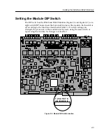
Setting the Module DIP Switch
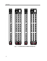
The DIP switch on the 9E428 and 9E429 Modules (Figure 2-1 and Figure 2-2), is an
eight-switch DIP located near the bottom left corner of the module. Each switch is
set according to the functions described in Table 2-1. If switch settings are
changed, the processor on the module must be reset, using the reset switch or
repowering the module, for changes to take effect.
Figure 2-2. Module DIP Switch location
1 2 3 4 5 6 7 8
Содержание FlowPoint 2100 12
Страница 1: ...903number SmartSwitch 9000 9E428 12 36 and 9E429 12 36 User s Guide...
Страница 2: ......
Страница 14: ...Introduction 1 6...
Страница 22: ...Installing the 9E428 and 9E429 Modules 2 8...
Страница 32: ...LANVIEW LEDs 4 4...
Страница 36: ...Specifications 5 4...