


9C300-1 Environmental Module Operation
3-10
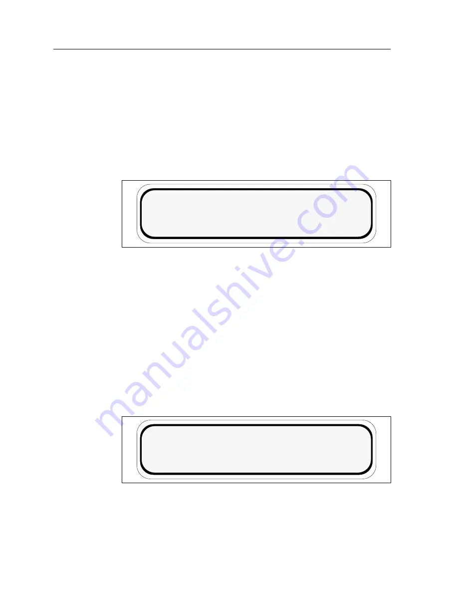
The Utilization Screen
The Utilization Screen, as shown in Figure 3-8, is the second screen of the
non-interactive mode.
Line 1 displays the screen heading.
Line 2 displays the FDDI 1 and FDDI 2 bus utilization.
Line 3 displays the INB A and INB B bus utilization.
Line 4 displays the system status.
Figure 3-8. The Utilization Screen
The Environment Screen
The Environment Screen, as shown in Figure 3-9, is the third screen of the
non-interactive mode.
Line 1 displays the screen heading.
Line 2 displays the external temperature of the chassis in both Fahrenheit and
Celsius and qualifies the temperature as COLD, COOL, NORM (normal), WARM
or HOT based on system parameters.
Line 3 displays the non-condensing humidity level of the chassis and qualifies it
as STATIC RISK, NORM (normal) or MOIST based on system parameters.
Line 4 displays the system status.
Figure 3-9. The Environment Screen
SYSTEM UTILIZATION
INB A _ _ _ _ _100%
SYSTEM STATUS NORMAL
FDDI 1_ _ _ _ _ 100% FDDI 2 _ _ _ _ _100%
INB B _ _ _ _ _ 100%
CHASSIS ENVIRONMENT
EXTERNAL TEMP xxx˚F xx˚C NORM
HUMIDITY xxx% NORM
SYSTEM STATUS NORMAL
Содержание Environmental Module TM 9C300-1
Страница 1: ...MMAC Plus 9C300 1 Environmental Module User s Guide...
Страница 2: ......
Страница 36: ...9C300 1 Environmental Module Operation 3 24...
Страница 46: ...EPIM Specifications A 8...
Страница 50: ...Uninterruptible Power Supply UPS B 4...


