Cabletron Systems Cyber SWITCH 1000 Скачать руководство пользователя страница 77

IPX R

OUTING

 N

ETWORK

O

VERVIEW

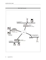
This sample network uses IPX protocol to allow remote devices and their servers to communicate. 
It illustrates a master network in which the central-site CyberSWITCH communicates with:

Remote bridges using a Remote LAN interface, and

A remote IPX router using a traditional WAN interface.

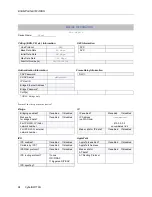
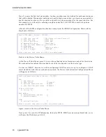
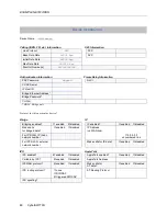
To better understand the layout of this network, refer to the following Network Topology 
Worksheet. Note that the central-site master network is in Detroit. Tampa and Orlando represent 
the bridged sites, and Dallas represents the remote WAN site.

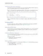
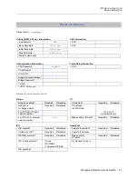
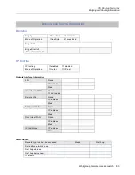
System details appear in the worksheets and are followed by the unique portion of this network’s 
configuration procedure.

B

USINESS

 A

SSUMPTIONS

All devices are PPP-compliant.

Central site is on a PBX; therefore, 9 required to dial out.

No File Servers at Tampa or Orlando sites.

Uses the On-node Device Database for authentication database.

Uses PAP to authenticate remotes; CHAP on central site.

Assumes Dallas Network supports Triggered RIP/SAP (i.e., compatible with central site).

Central site dials out only to Dallas; Tampa and Orlando dial in to central site.

Central site supports two BRI lines (4-port BRI card), with 5ESS custom switch configuration.

Assumes bridging enabled at system level (at central site) so that the device routes enabled 
network-layer protocols and bridges all other packets.

Uses no filtering; unrestricted mode.

I

NITIAL

 I

NSTALLATION

 S

TEPS

The initial steps in the CyberSWITCH installation process are basically the same no matter how 
detailed the network. These steps are:

completing the requirement worksheets

ordering  ISDN  service

powering on the system

accessing Release Notes

connecting an administration console

setting up Telnet access

upgrading system software

changing defaults to secure system

returning configuration to factory defaults

The chapters Accessing the CyberSWITCH and Upgrading System Software (in the User’s Guide) 
describe each of these steps in detail.

Содержание Cyber SWITCH 1000

Страница 1: ...WORKGROUP REMOTE ACCESS SWITCH EXAMPLE NETWORKS Release 7 2 Cabletron Systems 603 332 9400 phone 603 337 3075 fax support ctron com...

Страница 2: ...ATED TO THIS MANUAL OR THE INFORMATION CONTAINED IN IT EVEN IF CABLETRON SYSTEMS HAS BEEN ADVISED OF KNOWN OR SHOULD HAVE KNOWN THE POSSIBILITY OF SUCH DAMAGES Copyright 1998 by Cabletron Systems Inc...

Страница 3: ...cs 1993 including one or more U S Patents No 4701745 5016009 5126739 and 5146221 and other pending patents Telenetworks Copyright 1991 92 93 by Telenetworks All rights reserved FCC NOTICE This device...

Страница 4: ...Control Council for Interference by Information Technology Equipment VCCI If this equipment is used in a domestic environment radio disturbance may arise When such trouble occurs the user may be requ...

Страница 5: ...Information 22 Bridging 22 IP Routing 22 Configure the CyberSWITCH 23 Configuring the Options 23 Configuring the Security 23 Save Configuration Files 26 Verify the Installation 27 IP Routing Network...

Страница 6: ...ging 62 IP Routing 62 Device Information 63 Configure SITE1 65 Configuring the System Options 65 Finishing the Security Configuration 73 Configure SITE2 74 Configuring SITE2 Options 74 Configuring Sec...

Страница 7: ...Initial Installation Steps 93 Resources 95 Lines 95 AppleTalk Routing 96 Configure the CyberSWITCH 98 Configuring the Options 98 Configuring Device Information 101 Configuring an AppleTalk Static Rou...

Страница 8: ...word and one device will not This network uses BRI lines IP Routing Network An IP routing network with devices accessing the network from their homes IP Routing Network with Remote Bridge Devices A sm...

Страница 9: ...matter how complicated the network These steps are completing the requirement worksheets ordering ISDN service powering on the system accessing Release Notes connecting an administration console sett...

Страница 10: ...5 and RS232 Lines Type Slot Switch type Synchronization type BRI 1 5ESS Ethernet_1 2 Name Slot Port Line type Call screen TEI SPID Directory number Line1 1 1 PPP Auto Line2 1 2 PPP Auto Line3 1 3 PPP...

Страница 11: ...ridge Filters Bridge Dial Out Known Connect List IP Routing X enabled disabled Mode of Operation router X IP host LAN Name IP address Mask Unnumbered WAN need don t need Remote LAN Name IP address Mas...

Страница 12: ...will next add the line information Press 2 at the Physical Resources Menu and press 1 to add a line First you will be prompted for the line name You will then be asked to select which slot and port y...

Страница 13: ...g enabled For reasons we provide below we want both bridging and IP routing enabled Under the Option Menu select the bridging option and follow the instructions to enable bridging This network is a br...

Страница 14: ...uration menu 2 Select IP host operating mode Note The IP operating mode can not be set to host unless bridging is enabled 3 When you select the IP host operating mode an abbreviated IP configuration w...

Страница 15: ...RIP v2 authentication key required only if the IP RIP v2 authentication control has been configured with a value other than No Authentication For more detailed information on the IP host operating mod...

Страница 16: ...uted On the CyberSWITCH Verify resources are operational Issue dr command Look for BRI line messages Look for LAN initialized messages Look for Bridge initialized messages Verify WAN Lines Available C...

Страница 17: ...ll four phone numbers If the first line is busy the next line is automatically used and so on until a free line is found A Hunt Group number can be arranged through your Service Provider INITIAL INSTA...

Страница 18: ...556789 13135559876 Bridge Ethernet Address 000123456789 Password JXF30 Bridge Ethernet Address 003456789000 Password None User Name Mike Mann User Name Pat Smith Bridges ISDN POWER SERVICE TX RX 10BAS...

Страница 19: ...LINES BRI Lines Hunt Group Number 13135551111 PRI Lines Type Slot Switch type Synchronization type BRI 1 NI 1 Ethernet_1 2 Name Slot Port Line type Call screen TEI SPID Directory number Line1 1 1 PPP...

Страница 20: ...idge Password JXF30 CLID s 13135551212 13135552121 Bridging enabled enabled disabled IP enabled enabled disabled Make calls for bridged data enabled disabled IP Address on WAN link For IP RLAN IP Sub...

Страница 21: ...Ethernet Address 003456789000 Bridge Password CLID s 13135556789 13135559876 Bridging enabled enabled disabled IP enabled enabled disabled Make calls for bridged data enabled disabled IP Address on WA...

Страница 22: ...Dial Out Known Connect List IP Routing X enabled disabled Mode of Operation router IP host LAN Name IP address Mask Unnumbered WAN need don t need Remote LAN Name IP address Mask Traditional WAN Name...

Страница 23: ...Link but can handle two calls one for each bearer channel For NI 1 switches the BRI line has two phone numbers one for each bearer channel and each phone number has its own SPID You must enter the nu...

Страница 24: ...NG THE DEVICE LEVEL DATABASE From the Security Menu press 3 to display the Device Level Database Menu To enable the On node Device Database press 1 and follow the on screen instructions Press 2 to con...

Страница 25: ...protocol The device Mike Mann uses HDLC protocol so we will press 2 The only other item on the Device ISDN Line Protocol Menu that this type of device needs is the maximum data rate We will accept th...

Страница 26: ...er information for both devices in our network has been entered SAVE CONFIGURATION FILES We have now configured all of the required information for a bridged system with Calling Line Id Security and B...

Страница 27: ...s an outline of which steps should be executed On the CyberSWITCH Verify hardware resources are operational Issue dr command Look for BRI line messages Look for LAN initialized messages Verify WAN Lin...

Страница 28: ...e steps are completing the requirement worksheets ordering ISDN service powering on the system accessing Release Notes connecting an administration console setting up Telnet access upgrading system so...

Страница 29: ...Todd Jones 192 1 1 3 Ralph Moose 128 1 1 2 Jill Smith ISDN LAN 131 1 0 0 Router 1 131 1 1 16 128 1 1 16 WAN Direct Host Interface and WAN Interface 192 1 1 1 Host Host Host Host SITE San Fran POWER SE...

Страница 30: ...Secret ___________________ RESOURCES LINES BRI Lines PRI Lines Type Slot Switch type Synchronization type BRI 1 NTT Ethernet_1 3 Name Slot Port Line type Call screen TEI SPID Directory number line1 1...

Страница 31: ...Ethernet Address Bridge Password CLID s Bridging enabled enabled disabled IP enabled X enabled disabled Make calls for bridged data enabled disabled IP Address on WAN link 192 1 1 2 For IP RLAN IP Sub...

Страница 32: ...dge Password CLID s Bridging enabled enabled disabled IP enabled X enabled disabled Make calls for bridged data enabled disabled IP Address on WAN link 128 1 1 2 For IP RLAN IP Sub network number 0 0...

Страница 33: ...Ethernet Address Bridge Password CLID s Bridging enabled enabled disabled IP enabled X enabled disabled Make calls for bridged data enabled disabled IP Address on WAN link 192 1 1 23 For IP RLAN IP S...

Страница 34: ...dge Password CLID s Bridging enabled enabled disabled IP enabled X enabled disabled Make calls for bridged data enabled disabled IP Address on WAN link 128 1 1 3 For IP RLAN IP Sub network number 0 0...

Страница 35: ...l Out Known Connect List IP Routing X enabled disabled Mode of Operation X router IP host LAN Name SanFran IP address 128 1 1 1 Mask Unnumbered WAN need don t need Remote LAN Name IP address Mask Trad...

Страница 36: ...line for each additional line The following sections provide instructions for completing the remaining configuration steps CONFIGURING THE CYBERSWITCH OPTIONS To begin the configuration of the system...

Страница 37: ...e you should enter is 128 1 1 1 You will then be asked for the IP Subnet mask information In our example we are using a Class B address without any subnetwork addressing that requires 16 bits of the a...

Страница 38: ...255 2 128 1 0 0 3 255 255 255 255 4 0 0 0 0 5 Specify Explicitly Enter a Transmit Broadcast Address from the above menu default 1 RET RIP Send Control 1 Do Not Send 2 RIP Version 1 3 RIP Version 1 Co...

Страница 39: ...or disabling host routes propagation The RIP host routes propagation scheme determines how the WAN local route will be propagated via RIP The default value is Host Routes Propagation is currently DIS...

Страница 40: ...in Menu CONFIGURING THE SECURITY This example has remote devices and the device information for each of those devices must be configured Device security is used and the remote devices are configured i...

Страница 41: ...ormation for our first device Rick Bear After the new device name has been specified a screen similar to the following is displayed Select 1 ISDN The ISDN Configuration Menu then displays preconfigure...

Страница 42: ...the displayed screen Configuration is now complete for device Rick Bear Following this example complete the entry of information for all remaining devices Device ISDN Line Protocol Menu Device Rick B...

Страница 43: ...NG THE NETWORK LOGIN INFORMATION This network doesn t require the use of a user level database so network login information configuration is not necessary SAVE CONFIGURATION FILES We have now configur...

Страница 44: ...tional Issue dr command Look for BRI line messages Look for LAN initialized messages Check for IP routing initialized message in log Verify WAN Lines Available Connect WAN lines Issue dr command Look...

Страница 45: ...ers at Carmel or Monterey sites Uses the On node Device Database for authentication database Uses PAP to authenticate remotes CHAP on central site Carmel and Monterey dial into Corporate Office Corpor...

Страница 46: ...HDLC Bridge Host Host Carmel Monterey IP Sub Network Number 131 12 10 0 Remote Satellite Offices POWER SERVICE TX RX 10BASE T LAN B CHANNELS E1 ONLY B2 B4 B6 B8 B26 B28 B22 B24 B18 B20 B14 B16 B10 B1...

Страница 47: ...______________ CHAP Secret _______________ RESOURCES LINES BRI Lines PRI Lines Type Slot Switch type Synchronization type BRI 1 NTT Ethernet_1 2 Name Slot Port Line type Call screen TEI SPID Director...

Страница 48: ...Bridge Password q3bay CLID s Bridging enabled X enabled disabled IP enabled enabled X disabled Make calls for bridged data enabled X disabled IP Address on WAN link For IP RLAN IP Sub network number 1...

Страница 49: ...e Ethernet Address 222222222222 Bridge Password dharry CLID s Bridging enabled X enabled disabled IP enabled enabled X disabled Make calls for bridged data enabled X disabled IP Address on WAN link Fo...

Страница 50: ...ng X enabled disabled Mode of Operation X router IP host LAN Name CorpOffice IP address 128 1 1 1 Mask 255 255 0 0 Unnumbered WAN need don t need Remote LAN Name Satellites IP address 198 12 10 1 Mask...

Страница 51: ...egin the configuration of the system options press 2 at the Main Menu The options menu will then be displayed ENABLE DISABLE BRIDGING Whether or not to use bridging depends on network requirements The...

Страница 52: ...pt the default of 16 significant bits Press return to accept the default packet encapsulation type Ethernet Press return to accept the default of 1500 as the MTU size Press return to accept the defaul...

Страница 53: ...t 16 RET Enter the packet encapsulation type 1 for ETHERNET 2 for SNAP default ETHERNET RET Enter the MTU size in bytes default 1500 RET Transmit Broadcast Address 1 128 1 255 255 2 128 1 0 0 3 255 25...

Страница 54: ...e configured in the on node authentication database Device security using an on node authentication database are the default values Before beginning note the following This is a system configuration u...

Страница 55: ...ces press 2 On node Device entries Press 1 to configure the information for our first device Monterey You will be prompted for the device name followed by the Device Table Menu Select 1 ISDN The ISDN...

Страница 56: ...plicable for this example Return to the On node Device Entries Menu Configuration is now complete for the device Monterey Enter the device Carmel in the same way providing its Bridge Ethernet address...

Страница 57: ...he old NODE NEI file will be called NODE BAK After you save the configuration files press RET to exit the CFGEDIT program Reboot the system to activate your changes VERIFY THE INSTALLATION Steps on ho...

Страница 58: ...sheet This chapter discusses the configuration process for SITE1 and SITE2 Note that the Network Topology and the System Details worksheets are identical for both systems Each system has unique Routin...

Страница 59: ...st 2 LAN 2 128 3 3 4 Phone Number 913135553232 LAN Interface 128 3 3 1 ISDN CSX1200 POWER SERVICE TX RX 10BASE T LAN B CHANNELS E1 ONLY B2 B4 B6 B8 B26 B28 B22 B24 B18 B20 B14 B16 B10 B12 B30 L1 B1 B3...

Страница 60: ..._ _____ikcd98s_____ RESOURCES LINES BRI Lines PRI Lines Type Slot Switch type Synchronization type BRI 1 5ESS Ethernet_1 2 Name Slot Port Line type Call screen TEI SPID Directory number Line1 1 1 Auto...

Страница 61: ...ed Bridge Filters Bridge Dial Out Known Connect List IP Routing X enabled disabled Mode of Operation X router IP host LAN Name LAN1 IP address 128 1 1 1 Mask Unnumbered WAN X need don t need Remote LA...

Страница 62: ...wn Connect List IP Routing X enabled disabled Mode of Operation X router IP host LAN Name LAN2 IP address 128 3 3 1 Mask Unnumbered WAN X need don t need Remote LAN Name IP address Mask Traditional WA...

Страница 63: ...Secret ikcd98s IP Host ID Bridge Ethernet Address Bridge Password CLID s Bridging enabled enabled disabled IP enabled X enabled disabled Make calls for bridged data enabled disabled IP Address on WAN...

Страница 64: ...idge Ethernet Address Bridge Password CLID s Bridging enabled enabled disabled IP enabled X enabled disabled Make calls for bridged data enabled disabled IP Address on WAN link unnumbered For IP RLAN...

Страница 65: ...egin the option configuration press 2 at the Main Menu The options menu will then be displayed For this example we only need IP routing enabled The first thing to do disable bridging After that we wil...

Страница 66: ...work numbers for the WAN connections do not have to be created and therefore saving IP sub network numbers First we will add the LAN interface Press 2 to edit the IP Interface Information Press 1 to a...

Страница 67: ...nter the packet encapsulation type 1 for ETHERNET 2 for SNAP default ETHERNET RET Enter the MTU size in bytes default 1500 RET Transmit Broadcast Address 1 128 1 255 255 2 128 1 0 0 3 255 255 255 255...

Страница 68: ...ce you need to enter SITE2 s device name for the next hop device To do this you must already have configured device SITE2 Return to the Main Menu to begin the device configuration ADDING DEVICE SITE2...

Страница 69: ...le logical connection This sets an upper boundary for line and capacity utilization This upper boundary allows you to keep one remote device from crowding out other devices and using an unfair share o...

Страница 70: ...e configuring CHAP security we opt to configure a CHAP secret ikcd98s After the secret has been entered the Device Authentication Configuration Menu will appear as follows Again return to the Device T...

Страница 71: ...ss N when asked if this is the default route Next enter the destination IP address of the network to which you want to connect You should enter SITE2 s LAN Interface IP address 128 3 0 0 After you ent...

Страница 72: ...tination is reachable directly and therefore no intermediate router will be used Press return to accept the default metric value of 2 Host 1 File Server Internet Router LAN 1 128 1 1 8 128 1 1 3 128 1...

Страница 73: ...e remote devices are configured in the on node authentication database We enabled device security using an on node authentication database when we configured the SITE2 device To complete the security...

Страница 74: ...titled Configure SITE1 page 65 CONFIGURING SITE2 OPTIONS For this example we only need IP routing enabled Unlike the SITE1 we do not need to enable IP routing for the SITE2 IP routing is enabled as a...

Страница 75: ...on for SITE2 Return to the Main Menu save your configuration files and exit Restart the SITE2 to activate the changes VERIFY THE INSTALLATION Steps on how to verify the installation are detailed in th...

Страница 76: ...Check connectivity to local devices IP PING 128 3 3 4 host Check connectivity to SITE1 CALL DEVICE SITE1 Check connectivity to remote devices IP PING 128 1 1 8 host IP PING 128 1 1 3 server IP PING 1...

Страница 77: ...entication database Uses PAP to authenticate remotes CHAP on central site Assumes Dallas Network supports Triggered RIP SAP i e compatible with central site Central site dials out only to Dallas Tampa...

Страница 78: ...VICE TX RX 10BASE T LAN B CHANNELS E1 ONLY B2 B4 B6 B8 B26 B28 B22 B24 B18 B20 B14 B16 B10 B12 B30 L1 B1 B3 B5 B7 B25 B27 B21 B23 B17 B19 B13 B15 B9 B11 B29 B31 E1 D T1 D POWER SERVICE TX RX 10BASE T...

Страница 79: ...Secret df8sds33 RESOURCES LINES BRI Lines PRI Lines Type Slot Switch type Synchronization type BRI 1 5ESS Ethernet 1 3 Name Slot Port Line type Call screen TEI SPID Directory number line1 1 1 PPP Aut...

Страница 80: ...ridge Ethernet Address Bridge Password CLID s Bridging enabled enabled X disabled IP enabled enabled disabled Make calls for bridged data enabled disabled IP Address on WAN link For IP RLAN IP Sub net...

Страница 81: ...P Host ID Bridge Ethernet Address Bridge Password CLID s Bridging enabled X enabled disabled IP enabled enabled disabled Make calls for bridged data enabled X disabled IP Address on WAN link For IP RL...

Страница 82: ...hernet Address Bridge Password CLID s Bridging enabled X enabled disabled IP enabled enabled disabled Make calls for bridged data enabled X disabled IP Address on WAN link For IP RLAN IP Sub network n...

Страница 83: ...idge Dial Out Known Connect List IP Routing enabled disabled Mode of Operation router IP host LAN Name IP address Mask Unnumbered WAN need don t need Remote LAN Name IP address Mask Traditional WAN Na...

Страница 84: ...ic Services IPX routing X enabled disabled Internal network number 111abc LAN name External network number Remote LAN name External network number detroitlan 0100 remotelan 0128 Destination network nu...

Страница 85: ...nd the Device Level Database Menu will be displayed To enable the On node Device Database press 1 and follow the on screen instructions To add the remote devices press 2 On node Device entries Press 1...

Страница 86: ...ect a WAN Peer Type of ACTIVE Finally there is no need to change the default Spoofing Options Return to the Device Table Menu Device ISDN Menu Device dallasnet 1 ISDN Line Protocol PPP Point to Point...

Страница 87: ...ls refer to the Configuring IPX chapter Network Interface Background Information The bridging options for tampabr should now look like the following The configuration of device tampabr is complete Ret...

Страница 88: ...twork However you must configure both the LAN interface and the Remote LAN interface for access to Tampa and Orlando The configurations of both of these interfaces are described in the following secti...

Страница 89: ...ation do not send receive and respond This will allow the remote peer to see NetWare services when the remote bridge is connected When not connected the services will age out and eventually go away Th...

Страница 90: ...Current Configuration for INTERFACE remotelan Interface Type WAN Remote LAN IPX Network Number 0128 MTU bytes 1497 Encapsulation Ethernet 802 2 RIP Configuration Send Control Do Not Send Send Frequen...

Страница 91: ...Disable Based upon the display insure that both RIP processing and SAP processing are enabled Follow the on screen instructions to make any necessary changes Note that you may also specify the size of...

Страница 92: ...resources are operational Issue dr command Look for WAN board initialized messages Look for BRI line messages Look for LAN initialization messages Look for Bridge initialization messages Verify WAN L...

Страница 93: ...ions would be similar we do not describe SITE2 s configuration For further network layout clarification refer to the AppleTalk Routing Topology Worksheet INITIAL INSTALLATION STEPS The initial steps i...

Страница 94: ...ISDN MAC CSX1200 SITE2 POWER SERVICE TX RX 10BASE T LAN B CHANNELS E1 ONLY B2 B4 B6 B8 B26 B28 B22 B24 B18 B20 B14 B16 B10 B12 B30 L1 B1 B3 B5 B7 B25 B27 B21 B23 B17 B19 B13 B15 B9 B11 B29 B31 E1 D T...

Страница 95: ...roup Number 13135551111 PRI Lines Type Slot Switch type Synchronization type BRI 1 NI 1 N A Ethernet 1 2 N A N A Name Slot Port Line type Call screen TEI SPID Directory number Line1 1 1 Auto 313555111...

Страница 96: ...ame Network type extended nonextended extended nonextended extended nonextended Netwk range number AppleTalk address Zone name s Unnumbered WAN X need don t need MAC Dial In WAN Network type extended...

Страница 97: ...ecret hcaz IP Host ID Bridge Ethernet Address Bridge Password CLID s Bridging enabled enabled disabled IP enabled enabled disabled Make calls for bridged data enabled disabled IP Address on WAN link F...

Страница 98: ...the Data Link but can handle two calls one for each bearer channel For NI 1 switches the BRI line has two phone numbers one for each bearer channel and each phone number has its own SPID You must ente...

Страница 99: ...vice defined string that will identify the LAN port to the system administrator Enter lanport1 for the port name port number Enter 1 for the port number of the AppleTalk LAN port This is the port numb...

Страница 100: ...mes you can logically group nodes on an internet Each name can be configured to represent a logical group within that respective internet As indicated on the topology worksheet SITE1 uses two zones En...

Страница 101: ...following sections will help you configure each of these three areas for device SITE2 CONFIGURING DEVICE SITE2 S ISDN INFORMATION We will begin by specifying the type of device This device is an ISDN...

Страница 102: ...of eight calls connections running in parallel to open up bandwidth quickly 512 000 64 000 8 The value need not be a multiple of the base data rate For this example enter 384 000 for the maximum data...

Страница 103: ...preconfigured default values as shown below To complete the AppleTalk configuration for device SITE2 Select AppleTalk Address Because this device is over an unnumbered link enter 0 0 for the Ap pleTal...

Страница 104: ...y worksheet SITE2 s network range is 45 50 next hop s AppleTalk address The next hop is the device that provides access to the network across the WAN In this case SITE2 will provide access to the netw...

Страница 105: ...e Changes from the main CFGEDIT menu Follow the on screen instructions to save any configuration changes made The old configuration files will be stored in the CONFIG directory with a file extension o...

Страница 106: ...with PPP devices 77 remote bridging with security 17 simple bridging 9 F FCC notice 3 I IP operating mode example configuration 13 23 IPX configure users 85 Interface Information 88 triggered RIP SAP...

Отзывы: