background image

FDDI Devices

BRIM-F6 User’s Guide

Page A-13

Figure A-9. Optical Bypass Switch 

concentrator is a hub. It provides connections to the dual ring for 
single attached stations and controls their access to the ring. The network 
can optically bypass each main ring connection if the attached station 
becomes disabled or when the branch cable is disconnected.

Bridging devices for FDDI connect multiple FDDI networks and link an 
FDDI ring to a network that uses a different MAC layer protocol (Token 
Ring or Ethernet). A bridge does not expand an existing FDDI ring, it 
connects rings. Bridges that link two different MAC layer protocols, such 
as FDDI and Ethernet, typically use one of two bridging techniques, 
encapsulation or translation

Translation bridges translate frames from a non-FDDI MAC layer 
protocol to FDDI, allowing, for instance, an Ethernet station to talk to an 
FDDI station. Encapsulation bridges enclose the non-FDDI frames within 
the FDDI protocol. These bridges work in pairs – the sending bridge 
encapsulates the message and the receiving bridge strips the FDDI 
protocol, restoring the original frame. The bridge maintains routing 
information for filtering (prevent frames from crossing the bridge) or 
forwarding messages across the bridge. 

STATION

FDDI
RING

FDDI Dual

Optical Bypass

Switch

STATION

FDDI
RING

FDDI Dual

Optical Bypass

Switch

BYPASS STATE

OPERATIONAL STATE

Station Power Off

Station Power On

BRIM-F Book  Page 13  Monday, January 29, 1996  9:26 AM

Содержание Cabletron BRIM-F6

Страница 1: ...BRIM F6 USER S GUIDE...

Страница 2: ......

Страница 3: ...into a Hub 2 7 CHAPTER 3 USING LANVIEW 3 1 CHAPTER 4 SPECIFICATIONS 4 1 4 1 Fiber Optic interface 4 1 4 2 Cable Specifications 4 5 4 3 Twisted Pair Pinout Configuration 4 7 4 4 Environment 4 8 4 5 Saf...

Страница 4: ......

Страница 5: ...onality to various Cabletron MIMs and hubs e g the EMM E6 ESXMIM NBR 420 620 or MicroMMAC The BRIM F6 utilizes two FPIM FDDI Port Interface Module slots to provide you with the option of using multimo...

Страница 6: ...concludes with a list of related documentation Chapter 2 Installation describes how to install FPIMs into the BRIM F6 and how to install the BRIM F6 into a Media Interface Module MIM or a stand alone...

Страница 7: ...tating ring topology If one segment of the FDDI ring becomes disabled this dual ring configuration provides redundancy and restores ring continuity As a SAS the BRIM F6 connects to the primary ring on...

Страница 8: ...ents where appropriate but does not repeat them Cabletron Systems EMM E6 Installation Guide Cabletron Systems EMM E6 Local Management Guide Cabletron Systems ESXMIM Installation Guide Cabletron System...

Страница 9: ...eed the following tools 1 disposable wrist strap provided with any BRIM MIM or hub 1 Phillips screwdriver Caution Observe all static precautions while handling modules 2 1 Unpacking the BRIM and the F...

Страница 10: ...PIM into the connector on the BRIM F6 See Figure 2 2 Figure 2 1 Removing the FPIM Coverplate 3 Press down firmly on the FPIM until the pins slide all the way into the connector holes 4 Secure the FPIM...

Страница 11: ...on devices that support BRIM technology You can install a BRIM F6 in any device that supports BRIM technology e g EMM E6 ESXMIM NBR 420 620 or MicroMMAC The following subsections provide instructions...

Страница 12: ...screws and the BRIM coverplate Note The BRIM F6 requires an additional 24 pin ribbon connection MIMs that support BRIMs provide one slot that supports this connection Install the BRIM F6 in the BRIM s...

Страница 13: ...cial 24 pin ribbon connector in addition to the standard 96 pin BRIM connector This ribbon connector allows the BRIM F6 to use in line filtering functionality BRIM F6 XMT PWR RCV STS FPIM A WRP LNK TW...

Страница 14: ...igure 2 4 Installing the BRIM F6 Ribbon Cable Caution The ribbon cable connector only fits into the ribbon cable jack one way Fit the tab on the connector into the groove in the jack for correct cable...

Страница 15: ...1 Power down your hub 2 Disconnect all cables from the hub Note the port to cable connections 3 Remove the chassis cover Note Refer to specific hub documentation for instructions on removing the hub...

Страница 16: ...use in line filtering functionality To install the BRIM F6 ribbon cable 1 Insert one ribbon cable connector into the ribbon cable jack on the BRIM See Figure 2 4 Caution The ribbon cable connector onl...

Страница 17: ...M F6 LANVIEW LEDs PWR Power When ON this Green LED indicates that power is supplied to the BRIM STS Status This multi state LED can indicate the following Green The station attached to the port is con...

Страница 18: ...into one ring XMT Transmit When ON this Green LED indicates that the BRIM F6 is transmitting traffic to the FDDI network On a network with average traffic the XMT LED normally flashes RCV Receive Whe...

Страница 19: ...haracteristics Multimode Specifications Multimode Transmitter Optical wavelength 1330 nm typical Optical output 20 0 dBm minimum 14 0 dBm maximum Optical rise time 3 5 nsec maximum Optical fall time 3...

Страница 20: ...pical 100 sec maximum Deassert power 36 0 dBm typical 45 0 dBm minimum Deassert time 10 sec typical 350 sec maximum Hysteresis 1 5 dB minimum Single Mode Transmitter Optical wavelength 1330 nm typical...

Страница 21: ...14 0 dBm maximum Output rise time 3 nsec maximum Output fall time 3 nsec maximum Supply current 115 mAmps maximum Single Mode Receiver Signal Detect Assert power 33 0 dBm typical 31 0 dBm maximum Ass...

Страница 22: ...ir Transmitter Amplitude 1 080 Vpk maximum 0 920 Vpk minimum Rise time 2 nsec minimum 4 nsec maximum Fall time 2 nsec minimum 4 nsec maximum Rise Fall variation 0 5 nsec maximum Overshoot 5 maximum Dr...

Страница 23: ...SMF PMD ANSI standards define cable requirements as follows Deassert time 10 sec typical 350 sec maximum Shielded Twisted Pair Transmitter Amplitude 1 285 Vpk maximum 1 165 Vpk minimum Rise time 3 ns...

Страница 24: ...gth The PMD FDDI standard specifies the following Maximum total cable length 100 km 62 miles dual ring 200 km 124 miles wrapped Maximum multimode cable length between adjacent nodes 2 km 1 2 miles Sin...

Страница 25: ...Pair Pinout Configuration This section provides the RJ 45 pinout configuration for Unshielded Twisted Pair UTP and Shielded Twisted Pair STP Physical Layer Medium Dependent PMD ports Note When connec...

Страница 26: ...afety This unit meets the safety requirements of UL 1950 CSA C22 2 No 950 and EN 60950 the EMI requirements of FCC Class A and EN 55022 Class A and the EMC requirements of EN 50082 1 Note It is the re...

Страница 27: ...ity from electrical noise security and permits the use of longer cable segments These features make FDDI a viable alternative in LAN backbone applications or as a back end or front end network between...

Страница 28: ...primary and secondary data paths that operate as counter rotating rings Redundant rings facilitate recovery procedures in the event of a ring segment failure This recovery resembles that in Token Rin...

Страница 29: ...a flow the ring topology requires media that allows only one way traffic In practice an FDDI ring uses media that provides two fiber optic ring paths a primary ring and a secondary ring The secondary...

Страница 30: ...sical Layer Medium Dependent PMD standards and Physical Layer Protocol PHY Each section defines a unique entity of the FDDI station architecture and its operation The X3T9 5 entities perform many of t...

Страница 31: ...ayer protocol The PHY receives data frames from the MAC as a series of 4 bit symbols and encodes each 4 bit MAC symbol as a 5 bit symbol for transmission This encoding occurs to ensure each symbol has...

Страница 32: ...sing and generating and checking data check bytes The MAC generates two basic message formats tokens and frames Figure A 4 shows the layout for each message Control and format bits within the header d...

Страница 33: ...permit monitoring and control for a variety of station functions see Figure A 5 Figure A 5 SMT Management Organization SMT Frame Services generates and interprets special FDDI frames that assist in n...

Страница 34: ...he quality of the link and enforces connection rules screens marginal connections and supports maintenance activities A 5 FDDI Connection Rules One of the primary functions of SMT Connection Managemen...

Страница 35: ...t B If a cable failure severs concentrator 3 s connection to concentrator 2 CFM activates Port A A 6 FDDI Devices FDDI recognizes four station configurations SAS DAS DAC and SAC These configurations d...

Страница 36: ...id Station Configurations PHY PMD Single Attached Concentrator Dual Attached Concentrator PHY B PMD B PHY A PMD A PMD 3 Primary In Secondary Out Primary Out Secondary In PHY 3 PMD 2 PHY 2 PMD 1 PHY 1...

Страница 37: ...to Primary In and Primary Out fibers Types A and B allows dual attachment to the primary and secondary data paths of the main ring Type M allows for single attachment stations at a concentrator end o...

Страница 38: ...tity Since a DAS or DAC can match this configuration either could serve as a repeater when a main ring segment must extend beyond the 2 km maximum between nodes Together with Figure A 10 the following...

Страница 39: ...nt MAC layer protocols such as FDDI and Ethernet typically use one of two bridging techniques encapsulation or translation Translation bridges translate frames from a non FDDI MAC layer protocol to FD...

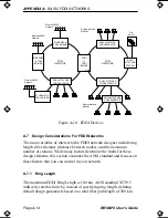
Страница 40: ...control in your network A 7 1 Ring Length The maximum FDDI Ring Length is 100 km ANSI standard X3T9 5 indirectly sets this limit by instead of specifying ring length defining default design parameter...

Страница 41: ...distance that a signal can travel on the ring and still be reliably received For FDDI networks using multimode fiber the maximum drive distance is 2 km For networks using single mode fiber the maximum...

Страница 42: ...nerated by 1000 physical connections determines this limit With the exception of optical bypass switches all FDDI devices count as two connections against the 1000 physical connection budget You can e...

Страница 43: ...Design Considerations For FDDI Networks BRIM F6 User s Guide Page A 17 Figure A 11 Physical Device Connections DAS 2 DAC 2 SAC SAS SAS SAS SAS SAS 16 PHYSICAL CONNECTIONS 2 2 2 1 1 2 2 2 2...

Отзывы: