Cabletron Systems 9C214-3 Скачать руководство пользователя страница 21


3-3

9C214-3 Power Supply Operation
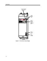
 

PWR Status LED


The PWR Status LED indicates the status of a power supply’s input and output. 
The possible states and descriptions of the PWR Status LED are listed in Table 3-1.


SMB Status LED


The SMB Status LED indicates the status of the diagnostic controller. The possible 
states and descriptions of the SMB Status LED are listed in Table 3-2.


Table 3-1. PWR Status LED  


LED Color

State

Description


Green

Functional

The 56-volt, 5-volt, and 3.3-volt outputs 
are within established tolerances.

Yellow

Crippled

Not fully operational (56-volt output is 
not within established tolerances due to 
lack of AC input).

Red

Fault

One of the system power supply outputs 
is out of regulation.

Off

Power off

Module powered off.

Table 3-2. SMB Status LED 


LED Color

State

Description


Green

Functional

Fully operational.

Yellow/Green

Booting 

Flashes yellow and green while booting.

Yellow

Testing

Power up testing being performed.

Yellow (Flashing)

Crippled 

Limited functionality of the diagnostic 
controller or fan failure.

Red

Reset

Normal power-up reset.

Red (Flashing)

Failed

Fatal error has occurred.

Off

Power off

Module powered off.

Содержание 9C214-3

Страница 1: ...9032529 01 SmartSwitch 9000 9C214 3 AC Power Supply Installation Guide...

Страница 2: ......

Страница 3: ...EVER INCLUDING BUT NOT LIMITED TO LOST PROFITS ARISING OUT OF OR RELATED TO THIS MANUAL OR THE INFORMATION CONTAINED IN IT EVEN IF CABLETRON SYSTEMS HAS BEEN ADVISED OF KNOWN OR SHOULD HAVE KNOWN THE...

Страница 4: ...in which case the user will be required to correct the interference at his own expense WARNING Changes or modifications made to this device which are not expressly approved by the party responsible fo...

Страница 5: ...Equipment for use in a Commercial or Light Industrial Environment We the undersigned hereby declare under our sole responsibility that the equipment packaged with this notice conforms to the above di...

Страница 6: ...Notice iv...

Страница 7: ...9000 Chassis 2 1 Powering Up the 9C214 3 Power Supply 2 3 Chapter 3 9C214 3 Power Supply Operation Operating Functions 3 1 System Diagnostic Controller 3 2 Internal Temperature Sensor 3 2 Power Suppl...

Страница 8: ...Contents vi...

Страница 9: ...or unpacking installing and powering up the 9C214 3 power supply Chapter 3 9C214 3 Power Supply Operation contains detailed information regarding the power supply operation Chapter 4 Specifications pr...

Страница 10: ...igure 1 1 The 9C214 3 Power Supply 207 264v 12A 50 60 Hz 9C214 3 100 50 0 Load POWER SUPPLY MODULE STATUS P W R S N B Status LED Power Supply SMB Status LED Power Supply Level Indicator LED Power Swit...

Страница 11: ...214 3 power supply This circuit protects the power supply from overheating if a thermal overload occurs Automatic recovery takes place after the thermal overload condition is corrected Load Sharing Ea...

Страница 12: ...from 40 60 volts DC This capability allows the SmartSwitch 9000 to operate from typical AC power and to charge batteries in a battery backup unit or operate on DC power such as found in a central off...

Страница 13: ...Cabletron Systems products in the network A description of your network environment layout cable type etc Network load and frame size at the time of trouble if known The device history i e have you re...

Страница 14: ...Introduction 1 6...

Страница 15: ...e the shipping box and packing materials in the event the power supply must be reshipped 2 Remove the power supply from the protective plastic bag Save the bag in the event the power supply must be re...

Страница 16: ...pushing the power supply in until its frame touches the surface of the SmartSwitch 9000 chassis Do not force the power supply in place If significant resistance is encountered before the frame is flu...

Страница 17: ...AC receptacle Turn on the power supply using the switch located near the power socket 3 The power supply uses a soft start feature and does a pre power diagnostic check Outputs become enabled within 5...

Страница 18: ...Installing the 9C214 3 Power Supply 2 4...

Страница 19: ...ply converts the 207 264 VAC to three different DC outputs for internal use by the system Each of these outputs is described below 56 volts supplied to the 48 volt DC System Power Bus for use througho...

Страница 20: ...a built in temperature sensor for monitoring its own internal temperature The results of the monitoring are available to the network manager via LCD as well as local and remote management Power Supply...

Страница 21: ...nd 3 3 volt outputs are within established tolerances Yellow Crippled Not fully operational 56 volt output is not within established tolerances due to lack of AC input Red Fault One of the system powe...

Страница 22: ...cription 1 5 Green 10 50 of power load being used No action necessary 6 9 Green 60 90 of power load being used No parallel power supply operational No action necessary 6 9 Yellow 60 90 of power load b...

Страница 23: ...ss A EN 55022 Class A VCCI Class I EMC requirements of EN 50082 1 IEC 801 2 ESD IEC 801 3 Radiated susceptibility IEC 801 4 EFT Service The 9C214 3 power supply is designed with the following service...

Страница 24: ...drawn through the chassis Universal AC Input Each 9C214 3 power supply accepts input voltage ranging from 207 264 volts at 50 60 Hz Input Voltage Each 9C214 3 power supply will draw the following cur...

Страница 25: ...4 3 Specifications Output Voltage Each 9C214 3 power supply is capable of generating the following output voltages 56 0 volts 35A 3 3 volts 17A 5 1 volts 18A...

Страница 26: ...Specifications 4 4...

Отзывы: