


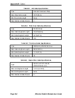


Appendix B: Cables
Page B-4
Ethernet Switch Module User Guide
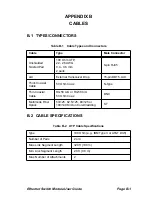
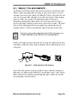
B.3.1
Crossover Wiring
Two Ethernet 10BASE-T devices can communicate only if the transmitter
on one device is connected to the receiver on the other device. This
reversal, or crossover function, can be implemented either in the wiring or
in the device itself.
When connecting two identical UTP ports (i.e., both crossover ports or
both straight-through ports), a crossover must be implemented in the
wiring. Refer to the following table for crossover pin assignments.
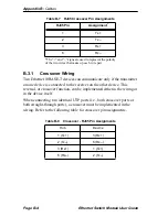
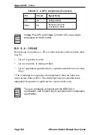
*The “+” and “–” signs are used to represent the polarity
of the two wires that make up each wire pair.
Table B-7
RJ45 Crossover Pin Assignments
RJ45 Pin
Assignment
*
1
Tx+
2
Tx–
3
Rx+
6
Rx–
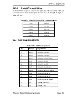
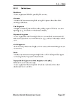
Table B-8
Crossover - RJ45 Pin Assignments
Hub
Device
1 (Tx+)
3 (Rx+)
2 (Tx–)
6 (Rx–)
3 (Rx+)
1 (Tx+)
6 (Rx–)
2 (Tx–)
Содержание 3E02-04
Страница 2: ......
Страница 30: ...Chapter 4 Monitoring Page 4 4 Ethernet Switch Module User Guide ...
Страница 36: ...Chapter 5 Diagnostics and Troubleshooting Page 5 6 Ethernet Switch Module User Guide ...
Страница 40: ...Chapter 6 Adding Swapping Modules Page 6 4 Ethernet Switch Module User Guide ...
Страница 44: ...Appendix A Technical Specifications Page A 4 Ethernet Switch Module User Guide ...
Страница 52: ...Appendix B Cables Page B 8 Ethernet Switch Module User Guide ...
Страница 54: ...Index Index 2 Ethernet Switch Module User Guide ...


