

INSTALLATION INSTRUCTION
FOR DLPS-15D
INSTALLATION:
* New Installation:
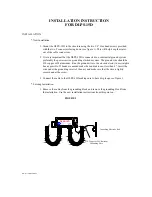
1. Mount the DLPS-15D to the structure using the two 1/4” Hex head screws provided,
with the two F connectors facing down (see figure 1). This will help keep the water
out of the cable connectors.
2. It is very important that the DLPS-15D is connected to a substantial ground system
preferably the power service grounding electrode system. The ground wire should be
#10 copper or #8 aluminum. Run the ground wire to the electrode (rod) in as straight a
line as possible. If bends are needed make the bend radius not less than 4”. Insert the
wire under the grounding screw of the unit, and make sure that the wire is tightly
secured under the screw.
3. Connect the cable to the DLPS-15D making sure to have drip loops, see figure 1.
* Existing Installation:
1. Remove the cables from the grounding block and remove the grounding block from
the installation. Use the new installation instructions from this point on.
FIGURE 1
DWG# 1015D000 REV B
DWG# 1015D00 REV C
CABLE INNOVATIONS
BRKDWN VOLTAGE 135V
DLPS-15D
PATENT # 5216569
R
L
U
75O SIGNAL
CIRCUIT PROTECTOR
LISTED 6P12
MHZ
5-1000
Grounding Electrode Rod
#10 Copper or #8 Aluminum
Grounding Wire