5. Useful LED combinations
The LEDs for the corresponding pins need to light up to make sure the desired mode is available. Please note
that shorted pins, diodes, active electronics or other faults/things inside the cable can provide false results.
Options A and B are for the two possible connector
I
orientations and can be inverted by flipping the cable at
connector
I
.
If D+ and D- are connected, they only light up on one side of the tester. This is for compatibility with older USB
connector generations and can be inverted by flipping connector
I.
Sources: https://en.wikipedia.org/wiki/USB-C
https://commons.wikimedia.org/wiki/User:Chindi.ap
A1
A2
A3
A4
A5
A6
A7
A8
A9
A10
A11
A12
B12
B1
B2
B3
B4
B5
B6
B7
B8
B9
B10
B11
RX1+
RX1−
VBUS SBU2
D−
D+
CC2
TX2−
VBUS
TX2+
GND
GND
TX1−
VBUS
CC1
D+
D−
SBU1
RX2−
VBUS
RX2+
TX1+
GND
GND
GND
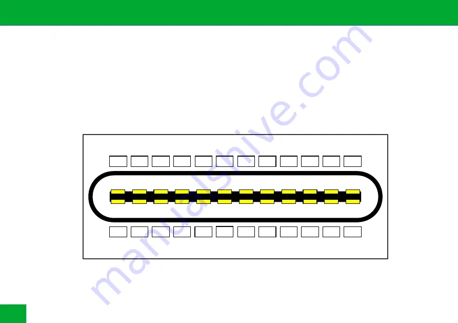
USB C receptable pinout (front view)
6
Содержание C2C v2.5k
Страница 1: ...Manual C2C caberQU v2 5k USB C to USB C cable tester caberqu com...
Страница 2: ......
Страница 9: ...7 Schematics C2C caberQU 9...
Страница 10: ......


