background image

13

4.6 

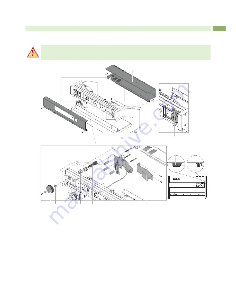
Changing the hub to main motor

Danger!

Danger to life and limb from power supply.


Befor open the device unlink the power!

4

5

6

7

8

9

12

11

10

1

2

3

13a

13b

rear view

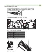
Fig.11      Dismount the hub to the main motor

1.  Swing lever (13) in position b to connect the blade with the motor and to relax spring (8) .

2.  Dismount front (1) and rear (2) cover.

3.  Loosen the three screws (3) and move the tension wheel (5) to the center to relax the belt.

4.  Loosen screw (4) and remove the belt gear (5) .

5.  Dismount cooling bracket (12) .

6.  Remover motor assembly (10) after loosening screws (11) .

7.  Remove snap ring (6) with a snap ring caliper.

8.  Pull out the hub (9) with spring (8), washer and snap ring (7) .

9.  Remove snap ring (7) with a snap ring caliper and remove washer and spring (8) . 


Mounting the new hub in reverse order. 

Test and Change Device Parts

Содержание MAESTRO 4S

Страница 1: ...Service Manual MAESTRO 4S PCB Separator ...

Страница 2: ...k www cab de for the latest update Terms and conditions Deliveries and performances are effected under the General conditions of sale of cab Service Manual for the following products Germany cab Produkttechnik GmbH Co KG Postfach 1904 D 76007 Karlsruhe Wilhelm Schickard Str 14 D 76131 Karlsruhe Telefon 49 721 6626 0 Telefax 49 721 6626 249 www cab de info cab de France cab technologies s a r l F 6...

Страница 3: ...the Linear Blade 11 4 4 Adjusting the Linear Blade 11 4 5 Check the Blade Alignment 12 4 6 Changing the hub to main motor 13 4 7 Changing the Control Panel Emergency Switch 14 4 8 Changing the Belt 14 4 9 Changing the Energy Track 15 4 10 Check the Sensors 15 4 10 1 Check the Sensors via Control Panel 16 4 10 2 Check the Sensors on PCB 17 5 Errors 19 6 Spare Parts Drawings 20 6 1 Side Parts C Prof...

Страница 4: ...fety rules However danger to the life and limb of the user or third parties and or damage to the device and other tangible assets can arise during use The device may only be used for its intended purpose and if it is in perfect working order and it must be used with regard to safety and dangers as stated in the operating manual The device is intended exclusively for separating pre scored PCB s Any...

Страница 5: ... expose it to moisture sprays of water mists etc Do not use the device in an explosive atmosphere Do not use the device close to high voltage power lines Work going beyond this may only be performed by trained personnel or service technicians Unauthorized interference with electronic modules or their software can cause malfunctions Other unauthorized work on or modifications to the device can also...

Страница 6: ...ase of programming Mileage Kilometer counter up to 99 99 km DEL Reset of the kilometer counter Power switch ON OFF Foot switch START Separation Safety switch Emergency stop Spannung 100 240 V 50 60 Hz Emission sound pressure level LpA 70 dB A Temperature humidity not condensing Operation 10 35 C 10 85 Stock 20 50 C 20 80 Transport 25 50 C 20 80 Weight 38 kg 46 kg Height Depth 434x425 mm Width 702 ...

Страница 7: ...9 Control Panel 2 Pulse Sensor 10 Emergency Switch 3 Carriage Sensor right Links 11 tension Wheel 4 Carriage 12 Linear Blade 5 Set knob for cutting depth 13 PCB Control 6 Upper Circular Blade 14 Main Motor 7 Power Supply 15 Clutch Main Motor 8 Energy Track 16 Motor Circular Blade Fig 1 Frontview Fig 2 Rearview ...

Страница 8: ...8 to check the blade position Commercial tools Allen key 1 5 2 0 2 5 5 0 mm Jaw wrench 5 5 mm Phillips head screwdriver size 1 Precision Snap Ring Caliper A0 Precision Snap Ring Caliper A1 Oscilloscope 3 3 Contents of Delivery 5 6 4 2 1 3 1 Maestro 4S 300 600 2 Power Cable 3 Dial Gauge Assembly 4 Food Switch 5 Hexagonal Wrench DIN911 2mm 6 Hexagonal Wrench DIN911 5mm Documentation Fig 3 Contents o...

Страница 9: ...6 blade on the highest position 4 Swing lever 6 in position a to release 5 Loosen screws 4 and remove table 1 by movements back and top 6 Loosen screws 8 7 Remove motor carriage with mounted motor 7 8 Hold the setting knob 5 and loosen the knurled nut 12 9 Remove blade 11 It s possible that the washer 10 are adhere on the blade Remove the Washer 10 from blade and take it back on the axle 9 10 Take...

Страница 10: ...blade carrier 1 is now disconnected 2 Rotate the pointer 2 with the knob 4 counterclockwise to position 16 3 Move the upper blade carrier 1 in the middle position of the lower blade 4 Loosen the screw 3 5 Move the knob 4 clockwise until the upper and lower blades are in a distance of 0 03 mm Use a thickness gauge 6 Swing the strut 5 clockwise until you reach the stop and tighten the screw 3 This a...

Страница 11: ...ew 4 2 Hold the linear blade 1 to avoid an uncontrolled fall of the blade 3 Loosen screws 3 The eccentric 2 will used for guiding and will not loosened 4 Pull out the linear blade 1 in direction of the device rear side from eccentric 2 5 Move out the linear blade 1 6 Mounting of the new linear blade in revers order 4 4 Adjusting the Linear Blade Warning Risk of cutting injury in handling of the li...

Страница 12: ... following a move of equipment or a change of blades it is advantageous to re check the alignment of the blades in relationship to one another For this purpose a dial gauge assembly Part No 8970208 is available as an option 1 2 3 4 5 6 7 6 7 4 10 9 0 1 Roller Blade 8930509 001 FR4 Fig 10 Check the blade alignment 1 Move the blade carrier 1 to the middle of its range of travel 2 Affix the dial gaug...

Страница 13: ... 2 Dismount front 1 and rear 2 cover 3 Loosen the three screws 3 and move the tension wheel 5 to the center to relax the belt 4 Loosen screw 4 and remove the belt gear 5 5 Dismount cooling bracket 12 6 Remover motor assembly 10 after loosening screws 11 7 Remove snap ring 6 with a snap ring caliper 8 Pull out the hub 9 with spring 8 washer and snap ring 7 9 Remove snap ring 7 with a snap ring cali...

Страница 14: ...emove it 7 Loosen nut 5 and remove the upper part 4 of the emergency switch X X Mounting of the control panel 3 emergency switch in reverse order 4 8 Changing the Belt 1 2 3 4 5 6 7 Fig 13 Changing the belt 1 Dismount front cover 1 2 Loosen the three screws 6 and move the tension wheel 7 to the center to relax the belt 2 3 Loosen screws 5 and remove the upper catch plate 3 4 Change the belt 2 and ...

Страница 15: ... cable from the cable retainer on the power supply 7 4 Loosen screws 4 and 8 5 Remove the energy track 7 X X Mounting the energy track 7 in reverse order 4 10 Check the Sensors Some sensors are integrated into the Maestro 4S to control the function and operation of the device This are reflex sensors with a switch reaction in case a surface are in front of approx 3mm distance For changing and adjus...

Страница 16: ...n und Gerät einschalten Durch Verschieben des Schlittens den zu prüfenden Sensor auslösen Zum Verlassen des Testmodus Gerät ausschalten i Hinweis Die Schlittensensoren lassen sich nur bei montierter Frontblende testen Sensor Tastenkombination um Testmodus auszuwählen Anzeige Taktsensor Taste home und plus gleichzeitig drücken Anzeige speed wechselt zwischen und Randsensor links Taste home und spee...

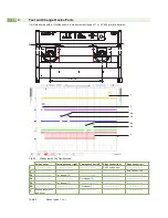
Страница 17: ...x 3mm distance For changing and adjusting is a 5 5 mm jaw wrench necessary 3mm Fig 17 Reflex sensor To check the function of a sensor are checkpoints on the PCB integrated 5 2 1 4 3 GND Fig 18 Checkpoints to check the sensor function Nr Bezeichnung Sensor 1 SSR 2 carriage sensor right 2 TS pulse sensor 3 RR side sensor right 4 SSL 2 carriage sensor left 5 RL side sensor left GND Ground Table 3 Sen...

Страница 18: ...ut length a b 7 6 1 2 3a 3b 4a 4b 5 Fig 20 Measurement by Oscilloscope Pulse sensor Carriage sensor right Carriage sensor left Edge sensor right Edge sensor left 1 End Position right 2 End Position Left 3a Cut stopper 6 2a Cut stopper 6 3b Cut stopper 7 4b Cut stopper 7 5 Start position to the end of cut Table 4 Sensor peak 1 cut ...

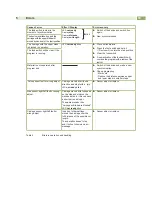
Страница 19: ... is running Material is not separated after program end X X Switch of the device and make a new synchronization X X Chang programing More cuts Reduce the distance between upper and lower blade in smaller steps Pulse sensor fault or wrong adjust Carriage moved short in one direction and stopt with a jerk LED not ready blink X X Sensor adjust or replace Side sensor right left fault or wrong adjust C...

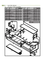
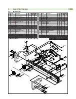
Страница 20: ... 8931182 001 Table 1 b 15 5903012 001 Spring Washer DIN137 A5 10 16 5902159 001 Screw DIN912 M5x12 10 No Part No Description PU Note Serial No from to 17 1 8933394 001 Linear Blade 1 a 17 2 8933682 001 Linear Blade 1 b 18 5902122 001 Screw DIN923 M6x6 10 19 8930886 001 Comb 1 20 5905079 001 Spring 1 21 5902501 001 Nut DIN934 M4 10 22 5903527 001 Snap Ring DIN471 10x1 10 23 5903005 001 Washer DIN90...

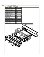
Страница 21: ...10 4374 46 5903004 001 Washer DIN125 A3 2 10 47 1 8930916 001 Sensor 1 a 47 2 8936916 001 Sensor 1 b No Part No Description PU Note Serial No from to 49 8930915 001 Edge Sensor 1 50 1 8936858 001 Beam 1 a 50 2 8936898 001 Beam 1 b 51 8936871 001 Bolt 1 52 1 8936814 001 PCB Control 1 4374 52 2 8936937 001 PCB Control 1 4375 53 8930985 001 Coupler 1 54 8936896 001 Bushing 1 55 5903062 001 Washer 3 2...

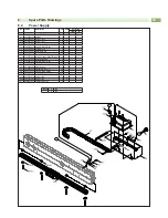
Страница 22: ...36871 001 Bolt 1 62 8936870 001 Control Panel 1 63 8930868 001 Tightener 1 64 8930854 001 Tensioning Wheel 1 65 1 8930961 001 Belt 1 a 65 2 8931181 001 Belt 2 b 66 8936804 001 Cable 1 67 5902304 001 Screw DIN7991 M4x6 10 68 8936834 001 Knurled Screw 1 69 1 8936821 001 Cover 1 a 69 2 8936867 001 Cover 1 b 70 5917167 001 Emergency Switch Push Button 1 71 8936837 001 Stopper 1 72 8936891 001 Washer 1...

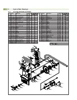
Страница 23: ...Nut DIN934 M4 10 76 5903033 001 Washer DIN125 A4 3 10 77 5903011 001 Toothed Washer DIN6797 A4 3 10 78 5534176 001 Cable Grounding 1 79 5902047 001 Screw DIN7991 M3x5 10 80 8936850 001 Bracket Power Supply 1 82 8936844 001 Ground Cable 1 83 5903028 001 Washer DIN433 6 4 10 84 5902178 001 Screw DIN912 M6x20 10 85 5902525 001 Nut DIN557 M6 10 86 1 5905183 001 Guide L 640 1 a 86 2 5905347 001 Guide L...

Страница 24: ...t Screw DIN913 M4x30 10 104 1 5902030 001 Screw DIN7991 M3x12 10 4504 104 2 5902010 001 Screw DIN912 M3x10 10 4505 No Part No Description PU Note Serial No from to 105 1 8931628 001 Set Knob 1 4504 105 2 8936943 001 Set Knob 1 4505 106 1 8931627 001 Guide Washer 1 4504 106 2 8936945 001 Guide Washer 1 4505 107 1 8931630 001 Plate 1 4504 107 2 8936944 001 Plate 1 4505 108 8936841 001 Bushing 1 110 ...

Отзывы: