background image

22

22

Operation

6.3 

Test Mode without Print Job

2

1

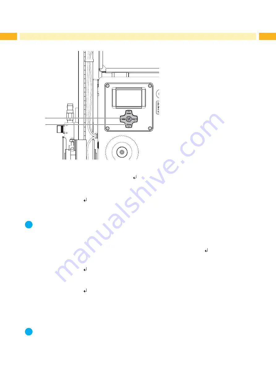
Fig. 23 

Test mode via Enter key

The whole labelling process can be simulated without the need of a print job or a connection to a computer by alter-

nately pressing the 

feed

 (2) key and the Enter key     (1) :


Press the 

feed

 key (2).

A blank label is fed. The vacuum at the pad as well as the supporting air (blow tube) are switched on. After the 

label has been picked up by the pad, the supporting air is switched off. 


Press the Enter key   (1).

The pad is moved to the labelling position.  A sensor signals when the labelling position is reached. The vacuum is 

switched off and the label is placed onto the product. Then, the pad is moved back into the starting position.

i

Notice!


Please use that test mode to adjust the parameter "Peel position" in the printer configuration.

6.4 

Test Mode with Print Job

That method allows to check labelling process with the real print data using the Enter key     (1).


Send a print job.

The test mode is executed in two half cycles :


Press the Enter key   (1).

Half cycle 1

A label is printed. The vacuum at the pad as well as the supporting air (blow tube) are switched on. After the label 

has been picked up by the pad, the supporting air is switched off.


Press the Enter key   (1) again.

Half cycle 2

The pad is moved to the labelling position.  A sensor signals when the labelling position is reached. The vacuum is 

switched off and the label is placed onto the product. Then, the pad is moved back into the starting position.

If the label is manually removed from the pad after the first half cycle, the half cycle 1 will be repeated when the 

pre-dispense key is pressed again. 

i

Notice!


Please use that test mode to adjust the peel-off offset in the software.

Содержание Hermes+ Applicator 1000

Страница 1: ...Applicator Operator s Manual 1000 ...

Страница 2: ...lease check www cab de for the latest update Terms and conditions Deliveries and performances are effected under the General conditions of sale of cab Operator s Manual Translation of the Original Version for the following products Germany cab Produkttechnik GmbH Co KG Postfach 1904 D 76007 Karlsruhe Wilhelm Schickard Str 14 D 76131 Karlsruhe Telefon 49 721 6626 0 Telefax 49 721 6626 249 www cab d...

Страница 3: ...inter Setup 14 4 2 Quick Mode for Setting the Delay Times 14 4 3 Configuration Parameters of the Applicator 15 5 Adjustments 16 5 1 Mechanical Adjustments 16 5 1 1 Moving the Pad 16 5 1 2 Adjusting the Parallelism between Pad and Dispense Edge 17 5 1 3 Aligning the Blow Tube 17 5 1 4 Opening the Holes on the Blow Tube 18 5 1 5 Adjusting the Stopper 18 5 2 Pneumatic Adjustments 19 5 2 1 Adjusting t...

Страница 4: ... device applicator mounted on a cab printer of the Hermes series is intended exclusively for applying suitable materials that have been approved by the manufacturer Any other use or use going beyond this shall be regarded as improper use The manufacturer supplier shall not be liable for damage resulting from unauthorized use the user shall bear the risk alone Usage for the intended purpose also in...

Страница 5: ...cal knowledge and tools required to do the necessary work There are various warning stickers on the device They draw your attention to dangers Warning stickers must therefore not be removed as then you and other people cannot be aware of dangers and may be injured 1 4 Safety Marking 2 1 1 Warning to damages by moving parts 2 Danger of crushing to hand and fingers by the moving pad Fig 1 Safety mar...

Страница 6: ...erent methods Stamp on The label is pressed directly onto the product Blow on The pad moves to a pre adjusted position approximately 10mm away from the product The label is blown onto the product by an air stream Roll on In the starting position the label is forwarded until touching the roller of the roll on pad At the labelling position the roller is pressed onto the product Then the label is app...

Страница 7: ...appli cator to the printer 4 Setting screw to adjust the angle between applicator and printer 5 Compressed air connector 6 Shutoff valve 7 Setting screw for vertical adjustment 8 Lower cylinder throttle valve 9 Pad application specific 10 Blow tube for supporting air 11 Vacuum throttle valve 12 Supporting air throttle valve Fig 2 Front view 2 Product Description ...

Страница 8: ...peration mode Blow on 2 Upper cylinder throttle valve 8 Lower cylinder throttle valve 10 Blow tube for supporting air 13 Sensor Start Position 14 Pneumatic cylinder 15 Interface to the printer 16 Sensor labeling position 17 Rings to reduce supporting air Fig 3 Rear view ...

Страница 9: ...ble in different standard sizes According to the size of the label the holes may be pierced by the customer For that purpose a piercing pin is included in the delivery contents On request tamp pads customized to the label sized are delivered 2 5 2 Roll on Pads Fig 6 Roll on pad A1411 bxh Roll on pads Type A1411 are only produced on request customized to the label size 2 5 3 Blow Pads Fig 7 Blow pa...

Страница 10: ...bels by vacuum When an universal tamp pad is delivered these holes are covered by the sliding foil and must be opened according to the label size For that purpose a piercing pin is included in the contents of delivery Attention Danger of stab injury in case of inappropriate use 1 2 3 4 2 mm Fig 9 Piercing the universal tamp pad 1 Place a label 1 to be operated on the bottom side of the pad 2 Note ...

Страница 11: ...e adapter profile with the in the shipment of the tamp included longer profile 1 2 6 5 3 5 2 3 1 4 1 2 3 Fig 10 Changing the attachment of the cylinder unit Fig 11 Changing adapter profile for tamp pad 116x102 and 116x152 1 Loosen screws 2 and move the pad assembly with the bearing 3 at the adapter profile 1 so that it s possible to work on the screws 5 2 Loosen screws 5 3 For tamp pad 116x102 and...

Страница 12: ...ain 4 Swing the applicator to the printer 5 Tighten the thumbscrew 5 6 Move up stopper of the position of transport safety for a free movement of the lift cylinder Mounting stopper Fig 12 Mounting and connection Attention The pad will immediately be moved in the starting position Danger of crushing to hand and fingers by the moving pad X X Do not reach into the zone of the moving pad and keep long...

Страница 13: ...Version Fig 15 Mounting the stopper When the applicator is delivered the stopper 1 is mounted on the rods 4 With this stopper the labelling position for the operation mode Blow on can be adjusted In delivery status the stopper is in a transport safety position Dependent of delivery time it s two different version of stopper The function are the same In the operation modes Stamp on and Roll on the ...

Страница 14: ...nfiguration and the function of the keys in the navigator pad Configuration manual of the printer or Operator s manual of the printer 4 1 Method for Changing the Printer Setup 1 Press menu key 2 Select Setup Machine param Applicator 3 Select and adjust the needed parameters 4 Return to the Ready mode 4 2 Quick Mode for Setting the Delay Times Beside the standard method for the printer configuratio...

Страница 15: ...l on time only at Mode of oper Roll on Dwell time max 5 s of the pad in the labelling position 0 ms Support delay on Setting the switch on delay max 2 5 s for the supporting air between print start and switching on the supporting air The delay prevents swirling at the front of the label and consequently avoids faults when the label is being picked up from the printer 0 ms Support del off Setting t...

Страница 16: ...guide rail that the distance between edge of the pad 6 to the edge of the dispense plate 7 of the printer is approximately 2 mm 3 Tighten screws 1 Height adjustment wide settings are described in section 3 3 and are only necessary in case of changing the pad type Fine adjustments 1 Loosen screw 3 2 Turn setting screw 2 Clockwise will move the pad higher Counterclockwise will move the pad lower 3 T...

Страница 17: ...4 with easily turning of the pad in a parallel position to the dispense edge 5 6 Tighten screw 3 5 1 3 Aligning the Blow Tube 1 2 2 3 3 Fig 18 Alignment of the blow tube 1 The blow tube 2 for the supporting air can be rotated around its axis That way the direction of the supporting air can be optimized 1 Loosen screw 1 2 Turn the blow tube 2 in that direction that the air current supports the suck...

Страница 18: ... surface 7 must not exceed 10 mm 5 Move the stopper 1 against the guide block 4 and tighten the screw 2 6 Insert the tubes into the appropriate push in fittings 1 5 7 Open the shutoff valve and switch on the printer Fig 20 Adjusting the stopper 5 1 4 Opening the Holes on the Blow Tube 1 2 The blow tube 1 has holes for the supporting air in regular distances of 15 mm When the applicator is delivere...

Страница 19: ...he downward speed turn counterclockwise the screw 4 at the lower valve 3 X X To increase the upward speed turn counterclockwise the screw 2 at the upper valve 1 i Notice The application pressure of the pad is mainly dependent on the downward speed of the pad X X In order to reduce the application pressure turn clockwise the screw 4 Attention The time for the downward movement of the pad may not ex...

Страница 20: ...porting air turn counterclockwise the screw at the valve 1 X X If necessary adjust the direction of the air current Aligning the Blow Tube Adjusting the vacuum With the valve 2 the vacuum to suck the label onto the pad can be adjusted X X Adjust the vacuum in such a way that the label is properly sucked by the pad X X To increase the vacuum turn counterclockwise the screw at the valve 2 i Notice W...

Страница 21: ...loading and for the re start after error treatment Parameter Peel Position in the printer configuration X X Check the basic setting in the printer setup Perform labelling cycles by alternately pressing the feed key and the pre dispense key Test Mode Using the Pre dispense Key without Print Job X X Adjust the Peel Position in such a way that the blank labels are peeled off completely from the liner...

Страница 22: ...parameter Peel position in the printer configuration 6 4 Test Mode with Print Job That method allows to check labelling process with the real print data using the Enter key 1 X X Send a print job The test mode is executed in two half cycles X X Press the Enter key 1 Half cycle 1 A label is printed The vacuum at the pad as well as the supporting air blow tube are switched on After the label has bee...

Страница 23: ...d der Fehler quittiert und der Applikator bewegt sich in die Grundposition Der Applikator ist betriebsbereit X X Press the feed key at the printer A synchronization feed is released The processed labels have to be removed manually After a few seconds the printer carries out a short backfeed to position the front edge of the next label at the printing line i Notice This synchronizing also has to be...

Страница 24: ...change of the switch state at the upper sensor at the cylinder between the start of the labelling process and the signal from the labelling position sensor Check the start position sensor service Vac plate empty Label has not been picked up properly by the pad or label fell off the pad before it could be placed onto the product If possible place the lost label onto the product manually Otherwise s...

Страница 25: ... thereby be made invalid Device Applicator Type 1000 Applied EC Regulations and Norms Directive 2006 42 EC on machinery EN ISO 12100 1 2003 EN ISO 12100 2 2003 EN ISO 14121 1 2007 EN 60950 1 2006 A11 2009 Person authorised to compile the technical file Erwin Fascher Am Unterwege 18 20 99610 Sömmerda Signed for and on behalf of the Manufacturer cab Produkttechnik Sömmerda Gesellschaft für Computer ...

Страница 26: ...amental regulations of the EC Rules for Safety and Health In the event of any alteration which has not been approved by us being made to any device as designated below this statement shall thereby be made invalid Device Applicator Type 1000 Applied EC Regulations and Norms Applied Norms Directive 2004 108 EC relating to electromagnetic compatibility EN 55022 2006 EN 55024 1998 A1 2001 A2 2003 EN 6...

Страница 27: ...ions 4 Intended Use 4 L Label height 6 Label width 6 O Overview 7 P Parameter 15 Peel off Mode 21 Peel Position 21 plastic rings 18 Pneumatic 19 Printer 12 Printer Setup 14 Print Job 22 R Roll on 6 Roll on Pads 9 S Safety 4 Safety Marking 5 Speed 19 Stamp on 6 Standard Operation 23 Stopper 13 18 Stop valve 12 SUB D 15 12 Supporting air 20 T Tamp Pads 9 Tamp Pad Type 1312 11 Test Mode 22 Throttle v...

Отзывы: