background image

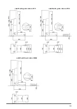
cablift mit Lenkrolle LR7

cablift mit Lenkrolle LR0

cablift mit Bockrolle BR80

0

/ 17

0

0

/ 17

0

Содержание 1000/LR75 8914390

Страница 1: ...Ausgabe Edition 04 06 cablift Bedienungsanleitung Operating Instructions...

Страница 2: ...B rstenleiste sch tzt die Spindel gegen Verschmutzung cab bietet Ihnen verschiedene Lastaufnahmen f r unterschiedliche Anwen dungen an Sonderplattformen und Aufnahmen fertigen wir nach Ihren W nschen...

Страница 3: ...eladen darauf dass das zu ladende Gut der Gr e und Bestimmung der benutzten Lastaufnahme entspricht Beachten Sie dazu auch die Ma e der Lastaufnahme Achten Sie beim Beladen darauf dass das Gewicht des...

Страница 4: ...50 mm 92 mm bei Bockrolle vorn 80 mm Sicherheitsabschaltung berlast mit Signalton bei Aufsitzen des Hebezeugs Netzspannung 85 264 VAC 50 60 Hz Netzkabell nge 5 m mit Aufrollvorrichtung Akkumulator Bl...

Страница 5: ...cablift mit Lenkrolle LR75 cablift mit Lenkrolle LR50 cablift mit Bockrolle BR80 2230 1750 2230 1750...

Страница 6: ...iegt in seiner Verantwortung wen er als Sachkundigen mit der Pr fung des Ger tes beauftragt Pr fung vor der ersten Inbetriebnahme Sicht und Funktionspr fung zur Sicherstellung dass sich das Ger t in e...

Страница 7: ...e1 M ngel festgestellt worden siehe Pr fungsbefund1 Blatt Nr ______ Die wiederkehrende Pr fung wurde durchgef hrt Es sind keine1 M ngel festgestellt worden siehe Pr fungsbefund1 Blatt Nr ______ Die wi...

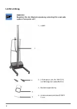
Страница 8: ...hren Sie die Originalverpackung unbedingt f r eventuelle sp tere Transporte auf 3 4 5 cablift 2 2 Schrauben Art Nr 8913723 zur Montage der Lastaufnahme 3 Bedienungsanleitung 4 Innensechskantschl ssel...

Страница 9: ...ng AUS Stellung EIN Montieren Sie die Lastaufnahme an den cablift Hinweise dazu finden Sie in der Montageanleitung der Lastauf nahme Schalten Sie den cablift ein Kontrollieren Sie den Ladezustand des...

Страница 10: ...staufnahme mit Taste 4 oder 5 auf vorgesehenen Haltepunkt fahren 2 3 s Programmiertaste 6 dr cken bis gelbe LED leuchtet dann loslassen Ein akustisches Signal schlie t den Vorgang ab Maximal k nnen 10...

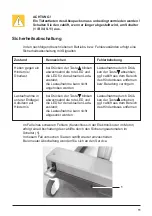
Страница 11: ...aste absenken ggf cablift aus dem Bereich des Hindernisses entfernen bzw Beladung verringern Lastaufnahme durch Dr c ken der Taste anheben ggf cablift aus dem Bereich des Hindernisses entfernen Sicher...

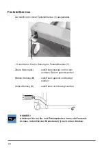
Страница 12: ...nkt werden Mittlere Stellung B cablift kann gelenkt und bewegt werden Untere Stellung C cablift kann nicht bewegt werden Feststellbremse Der cablift ist mit einer Feststellbremse 1 ausgestattet HINWEI...

Страница 13: ...ter 1 aus Laden des Akkupacks Schlie en Sie den cablift mit dem aufrollbaren Netzkabel 2 an die zentrale Netzversorgung an Schalten Sie den cablift am Schalter 1 ein W hrend des Ladevorgangs blinkt di...

Страница 14: ...d dann Steckverbinder 5 ab Entnehmen Sie den Akkupack 8 Setzen Sie den neuen Akkupack ein und montieren Sie das Abdeckblech Stecken Sie zuerst Steckverbinder 5 rotes Kabel und dann Steckverbinder 4 au...

Страница 15: ...EG Sicherheit von Maschinen EN ISO 12100 2 2003 EN 349 1993 EN 811 1996 Fahrbare oder ortsver nderliche Hub EN 1494 2000 ger te und verwandte Einrichtungen EG Niederspannungsrichtlinie 73 23 EWG EN 6...

Страница 16: ...rush ledge protects the spindle from contamina tion cab offers load suspension device retainers for different applications We manufacture special platforms and retainers on request Typ Part Nr Lifting...

Страница 17: ...and the form of the loaded product corresponds to the used load suspension device Attend in addition the dimension of the load retainer Do not exceed the maximal lifting capacity of the load retainer...

Страница 18: ...upper and lower end position block of platform escalating load change 50 Supply voltage 85 264 VAC 50 60 Hz Length of the power cord 5 m with roll up Accumulator maintenance free 7 2 Ah 24 VDC about...

Страница 19: ...19 cablift with guide rollers LR75 cablift with guide rollers LR50 cablift with fixed rollers BR80 2230 1750 2230 1750...

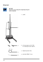
Страница 20: ...nt NOTICE Please be sure to keep the original packing for future shipment 2 2 Screws part no 8913723 for mounting the load retainer 3 Operating instructions 4 Allen Key DIN911 5 mm 1 cablift 5 cablift...

Страница 21: ...24 V Mount the load retainer on the cablift Please find the detail in the instruction sheet of the load suspension device Switch on the cablift Check the state of charge of the cablift see chapter Con...

Страница 22: ...charge state 30 The appropriate LED flashes if the cablift is in rest During lifting and lowering the appropriate LED is on 1 Operation Control The removable control panel is located on the handlebar...

Страница 23: ...acle Overload Load suspension device in lower end position Lowering the load retainer against an obstacle Symptoms When the key is pressed the red LED and the LED that indicates the current charge sta...

Страница 24: ...ing brake 1 Upper position A cablift can be moved and be steered with the front wheels Middle position B cablift can be moved and steered Lower position C cablift can not be moved A B C NOTICE Always...

Страница 25: ...that the power cord is rolled up slowly and equably When winding up the power cord un breaked it could be damaged 1 Maintenance We reccommend to check sthe state of charge at least every 30 days NOTIC...

Страница 26: ...ift 2 Loosen both screws 1 and remove the cover Use the Allen key 5 mm included in the delivery contents Loosen both screws 7 and remove the clamp 6 First take off plug 4 and then plug 5 red cable fro...

Страница 27: ...N ISO 12100 2 2003 EN 349 1993 EN 811 1996 Mobile or local changeable lifting devices EN 1494 2000 and similar fittings EC Voltage Regulations 73 23 EEC EN 60204 1 1997 EC Electromagnetic Compatibilit...

Страница 28: ...for any purpose other than the purchaser s personal use without the express written permission of cab Produkttechnik GmbH Co KG Karlsruhe Angaben zu Lieferumfang Aussehen Leistung Ma en und Gewicht en...

Отзывы: