


23
5 Adjustments
5.2.2
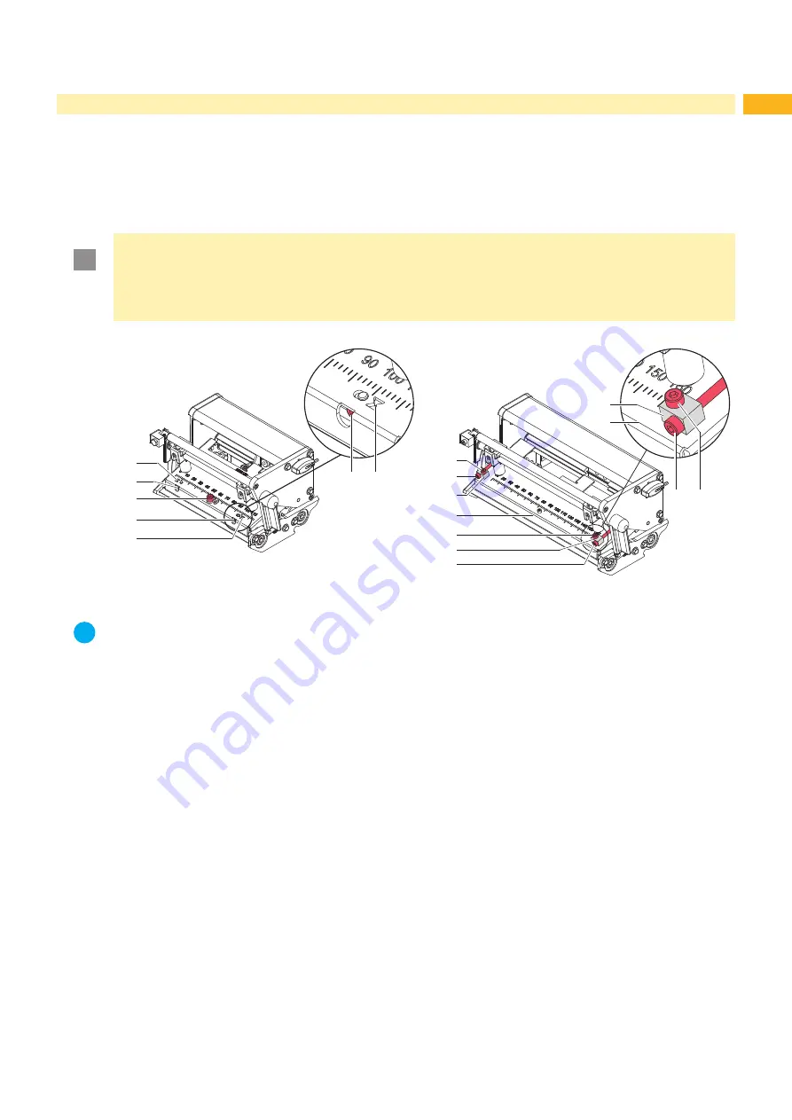
Adjusting the Printhead Position
In order to achieve the best possible print image the following printhead settings are necessary:
•
Align the heating line with the highest point of the print roller. Density of the print image is the greatest at this
point.
•
Set the parallelism of horizontal lines with the edge of the label.
!
Attention!
The printhead assembly can be damaged.
Attempting to adjust the printhead when the fixing screws (3) are tight can lead to defects at the printhead
assembly.
Always loosen the fixing screws (3) before adjusting the printhead.
1a
2a
3
2b
1b
2b 1b
2a
3
3
2b
2b 3
4
4
5
5
4
Fig. 23
Adjusting the printhead position (left PX4 / right PX6)
i
Notice!
Open and close the printhead lock after each step of the adjustment.
1. Check the alignment of the printhead on a output of a test print - parallelism printed lines to the label corner.
2. If the printhead is not aligned properly, loosen the screw (3) about one quarter turn.
3. If the printhead is not aligned properly, use the screws (2) to align at PX4 the lines on the printhead with the tips of
the grooves (1) respectively at PX6 front edge of the printhead mounting bracket with the front edge of the slides.
- Screw (2a) effects the inner half of the printhead, and screw (2b) the outer half.
- Turning clockwise moves the printhead at PX4 forward, at PX6 backward.
4. Create print samples with the test function
Test grid
(
Configuration Manual) or a similar print pattern.
5. If the horizontal lines in the test grid are not parallel with the label edges, adjust the parallelism with the
screws (2).
6. Set the best possible image quality by maintaining parallelism via turning the screws (2a) and (2b) in an alter-
nating fashion.
Differences in the density between the two sides are still permissible.
7. Tighten the screws (3).
8. When the parallelism of the printhead is set, continue with the adjustment of the printhead pressure
5.2.3 on
page 24.
Содержание PX Series
Страница 1: ...Made in Germany Service Manual PX Print Module ...
Страница 35: ...35 8 Layout Diagram PCB CPU Fig 36 Layout diagram PCB CPU components side ...
Страница 36: ...36 36 8 Layout Diagram PCB CPU Fig 37 Layout diagram PCB CPU soldering side ...
Страница 38: ...38 38 This page is intentionally left blank ...


