background image

For the antenna cable installation, you have three options :


1)  Determine a cable route that does not require deck penetration; 
or   
2)  Cut the cable to permit deck penetration , and rejoin the cable 
using NEWMAR splash proof junction box Model BX-1 or 
equivalent available at your local marine supply store;  
or 
3)  If you choose not to cut the cable, you may use a waterproof 
cable feed-through deck fitting for use with cable with installed 
cable connector, NEWMAR Model CCX-P or equivalent, also 
available at your local marine supply store. 
  
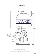
Ensure that the antenna unit will be adequately protected from 
lines that may foul on the unit and either damage the cable or the 
antenna unit.  
 
Plan a route for the connecting cable to the display unit, ensuring 
the cable is of adequate length to reach the rear of the display unit  
without putting tension on the cable. Also insure the cable is 
fastened securely so it will not become caught in nearby 
machinery. Try to avoid running the connecting cable in close 
proximity to power cords or generators carrying alternating 
current. The recomended procedure is to temporarily install all 
components of the antenna on the vessel in the planned positions. 
Check to ensure the unit functions properly and receives only 
minimal interference from other transmitting equipment, 
including any marine band or CB radios on the vessel. 
 
 If the location proves to be inadequate due to interference, find 
another more suitable location. If the location proves to be 
adequate, attach it permanently in position . This is accomplished 
by fastening the antenna unit base securely to the mounting 
surface , and then securing the antenna unit to the base .  
 
Most threaded antenna mounts are accepted by the base .  
Secure the connecting cable along the planned route so as to not 
interfere with anything. 


Page# 6 

Содержание 60

Страница 1: ...0 INSTALLATION AND OPERATION MANUAL SURVIVAL SAFETY ENGINEERING INCORPORATED 321 NAVAL BASE ROAD NORFOLK VIRGINIA 23505 USA Phone 757 480 5508 Toll Free 888 475 5364 Email survivalsafety cox net www s...

Страница 2: ...ector principles as the Model 100 Units that have performed so well under rigorous conditions for the U S Navy WARNING This device is intended for use as an aid to collision avoidance only It does not...

Страница 3: ...ule This Manual INDEX Warning Page 2 Components Page 3 How your C A R D system works Page 4 Antenna Installation Page 5 6 Antenna Unit Page 7 Control Module Warning Page 8 Control Module Page 9 Operat...

Страница 4: ...hat your target is approximately 45 degrees off your starboard bow and so on around the display The C A R D Radar Detector cannot determine the distance a scanning ship is away from your vessel but si...

Страница 5: ...nted with the base of the antenna down Mounting the antenna upside down will result in the alarm displayed on the opposite side of the vessel on the display unit If such a mounting procedure is applic...

Страница 6: ...ay unit without putting tension on the cable Also insure the cable is fastened securely so it will not become caught in nearby machinery Try to avoid running the connecting cable in close proximity to...

Страница 7: ...ANTENNA Page 7 Stern Rail Mount preferred Antenna Mounts available at most marine stores...

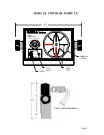
Страница 8: ...t location where you can observe the display Connect the power cable to a reliable power source of 12 volts D C It is suggested that you run the power cable to your distribution panel and not parallel...

Страница 9: ...Marine Radar Detector Survival Safety Enginee ring I nc ON AUDIO HI OFF LOW MODE L06 0 8 75 Gain Control Audio Heads Up Display Display Bars Page 9 DISPLAY CONTROL MODULE Power Antenna Cable...

Страница 10: ...l straight as a small radar on a low range setting Keeping in mind the fact that a C A R D does not finitely measure range overall range reception is adjustable by changing the sensitivity control kno...

Страница 11: ...he shell covering plug Locate pin 7 this is the only one without a wire Connect a wire to the negitive side of the buzzer The positive side of the buzzer is connected to the positive side of your batt...

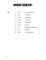
Страница 12: ...1 Red B to the antenna 2 Blue Aft Detector 3 White Stbd Detector 4 Green Port Detector 5 Brown Fwd Detector 6 Black Power B 7 NC Negative for external alarm 8 Red Power B 9 Black B to the antenna Page...

Страница 13: ...nguish is the point of the highest sensitivity This is much like setting the squelch on a VHF Marine Radio If a light stays on steadily it indicates that the sensitivity adjustment knob on the control...

Страница 14: ...NOTES Page 14...

Страница 15: ...charge This Warranty does not apply where repairs have been made or attempted by others repairs are required because of normal wear and tear the unit has been abused misused or improperly installed a...

Страница 16: ......

Отзывы: