Type 4
Equipment is energized. Energized circuits are exposed and inadvertent
contact with uninsulated energized parts is possible. Potential exposu-
res are greater than 30 volts rms, 42.4 volts peak, 60 volts dc, or 240
volt-amp in dry locations. Potential exposures to radio-frequency cur-
rents, whether induced or via contact, exceed the limits in Table A5-1
of Appendix 5 (SEMI S2 guideline).
Lock Out/ Tag Out procedure (Type 1 of
electrical work)
l
Stop the pump with the remote control (press on STOP button du-
ring 10s)
l
Press on emergency stop button
l
Switch off the main disconnect switch
l
Switch off the customer’s power supply
l
Switch off the water and nitrogen quick connections (inlet first,
then outlet)
l
Put the label or warning board “Maintenance processing” on or
next to the pump
Safety Lockout procedure
l
Take off the label or warning board “Maintenance processing”
l
Check the cooling liquid and oil levels according to the chapters
“Checking the oil level” and “Checking the cooling liquid level”
l
Switch on the main disconnect switch
l
Release the emergency stop button
l
Switch on the water and nitrogen quick connections (outlet first,
then inlet)
l
Start the pump with the remote control (press on START button)
Emergency off circuit description
l
The Emergency off circuit may be opened by pressing on emergen-
cy stop button. If this element shows, then the pump will immedia-
tely stop. The PLC will remain energized to save the pump status.
l
If the emergency stop button was pressed, check the start up of
the pump then release this button to restart the pump. Press on
Start button on the remote control, the pump will restart.
Lock out/ Tag out for hydraulics and pneumatics
u
Hydraulics: cooling water
u
Pneumatics: nitrogen
Lock Out/ Tag Out procedure (Type 1 of
electrical work)
l
Stop the pump with the remote control (press on STOP button du-
ring 10s)
l
Press on emergency stop button
l
Switch off the main disconnect switch
l
Switch off the customer’s power supply
l
Switch off the water and nitrogen quick connections (inlet first,
then outlet)
l
Put the label or warning board “Maintenance processing” on or
next to the pump
The end user is responsible for providing energy isolation capabilities
on the water and nitrogen
Transport
The COBRA DS vacuum pumps are tested and checked in our factory
before careful packing. Check the packaging for transport damage
when the goods arrive. The pump can withstand temperatures bet-
ween -25°C and +55°C during transport.
Transport in packed state
Packed on a pallet, the vacuum pump can be moved with a hand for-
klift truck.
Transport in unpacked state
The vacuum pump is fastened to the pallet with fixing pins:
u
Unscrew the fastening nuts underneath the pallet.
CAUTION
Do not work, walk or stand under suspended loads.
CAUTION
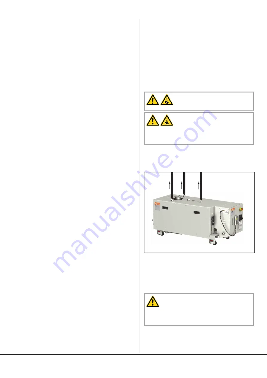
Please check out the weight of the vacuum pump before lifting it up
(see "Technical Data").
Use adequate lifting gear for this.
NOTE:
The suspension eyes are located at about the center-of-gravity
of the vacuum pump. If the vacuum pump is equipped with accessories
that could influence the center-of-gravity, this must be taken into ac-
count when lifting and a belt must additionally be attached to a speci-
fic point.
l
Fasten the hoist to the suspension eye(s) on the cylinder
l
Use a hoist that is equipped with a hook and safety lock
l
Lift the vacuum pump
If the pump is fastened to a pallet with fixing pins:
u
Unscrew the fixing pins in the base frame
CAUTION
In case of a vacuum pump filled with oil, make sure that by lifting
the inclination angle of the vacuum pump do not exceed 5° from
the horizontal. In case of too high inclination (>5°), risk of oil leak
within the work area.
Make sure before every transport using the appropriate lifting mean
that the inclination of the vacuum pump is less than 5°.
The packaging material must be disposed of in accordance with local
and national regulations.
DS 0600 E
Transport
0870772383 (En)
Page 7
Содержание COBRA DS 0600 E
Страница 22: ......


