


18
Installationandwiring
Type 8228
8.4 Wiring the device
Danger
risk of injury due to electrical voltage.
▶
Shut down the electrical power source of all the conductors and
isolate it before carrying out work on the system.
▶
If a 12...36 V DC powered version is installed either in a wet
environment or outdoors, all the electrical voltages must be of
max. 35 V DC.
▶
All equipment connected to the device shall be double insu-
lated with respect to the mains according to the standard
IEC 61010-1:2010.
▶
Observe all applicable accident protection and safety regula-
tions for electrical equipment.
• Use a filtered and regulated 12...36 V DC power supply.
• Make sure the installation is equipotential (see chap. 8.4.2).
• Use shielded cables with a temperature limit of 80 °C
minimum.
• Do not install the connection cables near high voltage or
high frequency cables; If this cannot be avoided, observe
a min. distance of 30 cm.
• Protect the power supply of the device with a 100 mA
time-delay fuse and a switch.
• Protect the power supply of each transistor output with a
750 mA fuse.
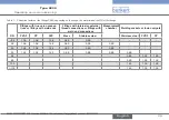
8.4.1 Assembling the male or female fixed
connector (available as an accessory)
4
3 2
1
→
Unscrew the nut [1] on the
body [4].
→
Insert the cable into the
nut [1], the cable clamp [2]
and the seal [3], and then
into the body [4].
5,5
11,5
20
5,5
11
5
20
5
→
Strip 20 mm of the cable.
→
Cut the central wire (earth)
so that its length is equal to
11.5 mm.
→
Expose 5.5 mm of the wires
on the stripped cable.
→
Put each wire into the
appropriate terminal of
the terminal block [5] (see
chap. 8.4.3 or 8.4.4).
→
Tighten the terminal
block [5] wired to the body
[4].
→
Tighten the connector
nut [1].
Fig. 9:
Assembling the M12 multi-pin connector (not provided)
English
Содержание 8228 ELEMENT
Страница 32: ...www burkert com ...