Operating Instructions
Bedienungsanleitung Manuel d‘utilisation
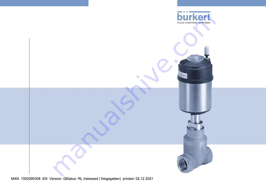
Type 2101
2/2 way globe valve2/2-Wege-GeradsitzventilVanne à siège droit 2/2 voies
Страница 1: ...Operating Instructions Bedienungsanleitung Manuel d utilisation Type 2101 2 2 way globe valve 2 2 Wege Geradsitzventil Vanne à siège droit 2 2 voies ...
Страница 2: ... right to make technical changes without notice Technische Änderungen vorbehalten Sous réserve de modifications techniques Bürkert Werke GmbH Co KG 2008 2021 Operating Instructions 2112 13_EU ML_00806076 Original DE ...
Страница 3: ...n 9 7 TECHNICAL DATA 11 7 1 Conformity 11 7 2 Standards 11 7 3 Type label 11 7 4 Operating conditions 12 7 5 General technical data 16 8 INSTALLATION 17 8 1 Safety instructions 17 8 2 Before installation 18 8 3 Installation 19 8 4 Pneumatic connection 22 8 5 Start up 23 8 6 Disassembly 23 9 ELECTRICAL CONTROL UNIT 23 10 MAINTENANCE CLEANING 24 10 1 Safety instructions 24 10 2 Maintenance work 24 1...
Страница 4: ...se instructions the unit bar stands for relative pressure The absolute pressure is stated separately in bar abs 1 OPERATING INSTRUCTIONS The operating instructions describe the entire life cycle of the device Keep these instructions in a location which is easily accessible to every user and make them available to every new owner of the device WARNING The operating instructions contain important sa...
Страница 5: ...rrect transport correct storage and installation as well as careful operation and maintenance The exhaust air can be contaminated by lubricants in the actuator Only use the device as intended 3 BASIC SAFETY INSTRUCTIONS These safety instructions do not take account of any contingencies or events which may occur during installation operation and maintenance of the devices local safety regulations t...
Страница 6: ...e any changes to the device and do not subject it to mechanical stress Transport install and dismantle heavy device only with the aid of a second person and using suitable tools Danger due to loud noises Depending on the usage conditions the device may generate loud noises Detailed information on the probability of loud noises is available from the respective sales department Wear hearing protecti...
Страница 7: ...id and gaseous media Using neutral gases or air control media it controls the flow of water alcohol oil fuel hydraulic fluid saline solution lye organic solvents and vapour flow media One special characteristic of the globe valves is the screwed in seats which can be used to reduce the seat size in particular for the control valve Type 2301 Definition DN DN refers to the nominal diameter of the se...
Страница 8: ...aximum pressure range on the type label For neutral gases and liquids up to 25 bar Steam up to 230 C Hot water up to 200 C Aggressive media 6 STRUCTURE AND FUNCTION 6 1 Structure The globe valve consists of a pneumatically actuated piston actuator and a 2 way body The actuator is made from polyphenylene sulphide PPS The proven self adjusting packing gland guarantees a high degree of tightness The ...
Страница 9: ... the swivel plate A spindle con nected to the actuator piston transmits the force 6 2 1 Control functions CF WARNING For control function I risk of pilot pressure failure With control function I the control unit and reset are pneumatic No defined position is reached during a pressure failure To ensure a controlled restart of the device first apply pilot pressure and then activate the medium Contro...
Страница 10: ... 1 2 Marking on the housing CFA CFB CFI Image 3 Flow direction below seat idle on off closing against medium 6 2 3 Flow direction above the seat The valve is closed with the medium flow via spring force control function A CFA Because the medium pressure is above the swivel plate it helps the valve close and also contributes to sealing the valve seat The valve opens via pilot pressure WARNING Risk ...
Страница 11: ...DN65 15 bar 7 3 Type label Example 00253282 2101 A PTFE Kv19 5 PS 8 5bar Tmed 10 C 185 C Flow 1 2 see manual for derating W17AL Made in Germany Image 5 Type label example WARNING Risk of injury from high pressure Important device specific technical data are listed on the type label Note the permitted pressure range on the device type label Example 00253282 2101 A PTFE Kv19 5 PS 8 5bar Tmed 10 C 18...
Страница 12: ...9 bar Tab 2 Derating the medium pressure as per DIN EN 12516 1 PN25 Temperature Medium pressure 29 38 C 19 bar 50 C 18 4 bar 100 C 16 2 bar 150 C 14 8 bar 200 C 13 7 bar 230 C 12 7 bar Tab 3 Derating the medium pressure as per ASME B16 5 ASME B16 34 Cl 150 Temperature Medium pressure 10 50 C 14 bar 100 C 14 bar 150 C 13 4 bar 200 C 12 4 bar 230 C 11 7 bar Tab 4 Derating the medium pressure as per ...
Страница 13: ...ion A flow direction below seat standard DN Maximum medium pressure bar Minimum pilot pressure bar Actuator size ø mm Actuator size ø mm 50 70 90 130 50 70 90 130 15 25 25 5 2 4 8 20 16 25 5 2 4 8 25 9 0 16 25 5 2 4 8 5 0 32 8 5 25 4 8 5 0 40 6 0 16 25 4 8 5 0 5 0 50 4 0 10 25 4 8 5 0 5 0 65 5 0 16 156 5 0 5 6 80 10 100 6 0 Tab 6 Medium and pilot pressure CFA standard 6 According to Pressure Equip...
Страница 14: ...7 Medium and pilot pressure CFA reduced spring force EC04 Required minimum control pressure depending on the medium pressure In the following graphs the required minimum control pressure is shown for control functions A B and I depending on the medium pressure Control function A flow direction above the seat Pilot pressure bar Operating pressure bar ø 50 CFA above seat 0 1 2 3 4 5 6 7 8 9 10 0 2 4...
Страница 15: ...0 2 4 6 8 10 12 14 16 DN40 DN50 DN65 Image 9 Pressure diagram actuator ø 90 mm control function A flow direction above the seat Control function B and I flow direction below seat 0HGLXP SUHVVXUH EDU 3LORW SUHVVXUH EDU DN25 DN20 DN15 ø 50 SFB SFI Image 10 Pressure diagram actuator ø 50 mm control function B and I flow direction below seat 0HGLXP SUHVVXUH EDU 3LORW SUHVVXUH EDU ø 70 SFB SFI DN15 DN2...
Страница 16: ...l technical data Actuator size See type label Control function See type label for description of control functions see chapter 6 2 Media Control medium Neutral gases air Flow media Water alcohols fuels hydraulic fluids saline solutions lyes organic solvents Materials Valve body 316L Actuator PPS and stainless steel Sealing elements FKM and EPDM Spindle seal PTFE V rings with spring compensation wi...
Страница 17: ...Risk of injury due to improper assembly Only trained technicians may perform installation work Perform installations using suitable tools only Risk of injury due to unintentional activation of the system and uncontrolled restart Secure equipment against unintentional activation Ensure that the system starts up in a controlled manner only For control function I risk of pilot pressure failure The va...
Страница 18: ...g actuator from the valve body For devices with welded connection NOTE For valves with a mounted control unit When welding the valve body into the pipeline the control unit must not be installed Uninstall the control unit from the actuator see chapter on installation in the operating instructions of the corresponding control unit Clamp valve body into a collet NOTE Damage to the seat seal or seat ...
Страница 19: ...bserve tightening torque see Tab 8 Tightening torques valve body nipple Dirt trap for devices with approval according to DIN EN 161 According to DIN EN 161 Automatic shut off valves for gas burners and gas appliances a dirt trap must be installed upstream of the valve The dirt trap must prevent the penetration of a 1 mm test pin If the approval also applies to the stainless steel valve body such a...
Страница 20: ...e UH1 96 402 from Klüber NOTE Damage to the seat seal or seat contour When installing the actuator the valve must be in the open position For control function A pressurise the pilot air port 1 with com pressed air 5 bar Valve opens Screw actuator into the valve body Observe tightening torque see Tab 8 Tightening torques valve body nipple 1 2 Pilot air port CFA CFB CFI Exhaust port CFA CFB pilot ai...
Страница 21: ...hich have not yet been installed For control function A pressurise the pilot air port 1 with com pressed air 5 bar Valve opens Counter with a suitable open end wrench on the wrench flat of the nipple Place a suitable open end wrench on the hexagon head of the actuator WARNING Risk of injury from discharge of pressure and escaping medium The body connection can loosen when rotated incorrectly Only ...
Страница 22: ...e a controlled restart of the device first apply pilot pressure and then activate the medium 8 4 1 Connecting the control medium If the position of the pilot air ports is unfavourable for installing the hoses these can be seamlessly aligned by rotating the actuator by 360 The procedure is described in chapter 8 3 3 Install control unit 1 2 Pilot air port CF A CF B CF I Exhaust port CF A CF B Pilot...
Страница 23: ...he control unit 8 6 Disassembly DANGER Risk of injury from discharge of pressure and escaping medium Dismantling a device which is under pressure is hazardous due to a sudden discharge of pressure or escaping medium Before disassembly shut off the pressure and vent all lines Procedure Disconnect the pneumatic connection Disassemble the device 9 ELECTRICAL CONTROL UNIT The Type 2101 valve can be co...
Страница 24: ...rt Secure the system against unintentional activation Following maintenance ensure a controlled restart WARNING For control function I risk of pilot pressure failure With control function I the control unit and reset are pneu matic No defined position is reached during a pressure failure To ensure a controlled restart of the device first apply pilot pressure and then activate the medium Risk of in...
Страница 25: ...ing parts 10 3 1 Replacing the valve seat The valve set consists of swivel plate with seal pin seal To change the valve set first remove the actuator from the valve body DANGER Risk of injury from discharge of pressure and escaping medium Dismantling a device which is under pressure is hazardous due to a sudden discharge of pressure or escaping medium Before disassembly shut off the pressure and v...
Страница 26: ... from the valve body Actuator Nipple Valve body Exhaust port CFA CFB Pilot air port CFI Pilot air port CFA CFB CFI Wrench flat for open end wrench Relief bore 2 1 Image 21 Part designation Replacing valve set Spindle pin Swivel plate seal Image 22 Valve set Support swivel plate on the cylindrical part using a prism or something similar Knock out pin using a suitable pin punch Pin punch ø 3 mm for ...
Страница 27: ...s For specific applications e g oxygen or analysis applica tions use approved lubricants only Before re installation grease nipple thread of the actuator e g using Klüberpaste UH1 96 402 from Klüber NOTE Damage to the seat seal or seat contour When installing the actuator the valve must be in the open position For control function A and I pressurise the pilot air port 1 with compressed air 5 bar V...
Страница 28: ...steps are described in chapter 10 3 1 Replacing the valve seat on page 25 The valve seat set consists of valve seat seal O ring depending on variant lubricant DANGER Risk of injury from discharge of pressure and escaping medium Dismantling a device which is under pressure is hazardous due to a sudden discharge of pressure or escaping medium Before disassembly shut off the pressure and vent all lin...
Страница 29: ...rect lubricants Unsuitable lubricant may contaminate the medium There is a risk of explosion in oxygen applications For specific applications e g oxygen or analysis applications use approved lubricants only Grease the valve seat thread using a lubricant e g Klüber paste UH1 96 402 from Klüber Manually screw attached valve seat into the body thread Tighten valve seat using torque wrench Observe tig...
Страница 30: ...sition For control function A and I Without control unit Pressurise pilot air port 1 with com pressed air 5 bar Valve opens With control unit Open the valve in accordance with the operating instructions of the control unit Screw actuator into the valve body Observe tightening torque see Tab 11 1 2 Pilot air port Pilot air port Image 25 Ports Tightening torques valve body nipple Orifice DN Tighteni...
Страница 31: ...ischarge of pressure and escaping medium Dismantling a device which is under pressure is hazardous due to a sudden discharge of pressure or escaping medium Before disassembly shut off the pressure and vent all lines WARNING Risk of injury due to using wrong tool Performing installation work using unsuitable tools is hazardous due to possible damage to the device To remove the actuator from the val...
Страница 32: ...s Place a suitable open end wrench on the wrench flat of the nipple Unscrew actuator from the valve body Actuator Nipple Valve body Exhaust port CFA CFB Pilot air port CFI Pilot air port CFA CFB CFI Wrench flat for open end wrench Relief bore 2 1 Image 26 Part designation Removing swivel plate Knock out pin using a suitable pin punch Pin punch ø 3 mm for 10 mm spindle diameter on the swivel plate ...
Страница 33: ...king gland SP10 SP14 series production status as of January 2013 Packing gland Spacer Spindle Packing gland tube SP22 VA spindle guide Image 30 Replacing the packing gland SP22 Series production status up to January 2013 Unscrew spindle guide using the installation wrench7 and an open end wrench Series production status as of January 2013 SP10 SP14 Unscrew spindle guide using a modified socket wre...
Страница 34: ... with the supplied lubricant Place individual parts on the spindle in the specified direction and sequence as shown in Image 31 Seal set for packing gland Push the packing gland into the packing gland tube Screw in spindle guide VA spindle guide again using the socket wrench open end wrench Observe tightening torque see Tab 13 Tightening torques spindle guide Support ring Upper chevron seals Upper...
Страница 35: ... plate Installing actuator on valve body For a description see Installing actuator on valve body on page 27 11 FAULTS Fault Elimination Actuator does not switch Pilot air port interchanged9 CFA Connect pilot air port 1 CFB Connect pilot air port 1 CFI Pilot air port 1 open Pilot air port 2 closing Pilot pressure too low Observe pressure specifications on the type label Medium pressure too high Obs...
Страница 36: ...ension The spring that ejects when the actuator opens may cause injuries The actuator must not be opened CAUTION Risk of injury and or damage due to incorrect parts Incorrect accessories and unsuitable spare parts may cause injuries and damage the device and the area around it Use only original accessories and original spare parts from Bürkert 12 1 Replacement part set The following replacement pa...
Страница 37: ...ant Order number Water outlet up to 200 C Order number high tempe rature outlet up to 230 C 15 5010 ø 50 216 433 372 661 372 662 ø 70 32 65 ø 90 216 435 372 653 372 655 ø 130 80 100 ø 130 252 545 200 23063 Tab 15 Seal set for packing gland 10 As of series production status January 2017 switch also possible for DN50 spindle ø 10 VA spindle guide for packing gland Spindle ø Orifice DN Actuator size ...
Страница 38: ...5 1 Seal 2 Swivel plate 3 Pin 4 Valve seat 5 Seal set for packing gland SP10 SP14 6 7 Valve set 6 Seal set for packing gland SP22 7 VA spindle guide SP22 Image 34 Spare parts 12 2 Installation tools Assembly key for packing gland only for dismantling packing gland until January 2013 Installation wrench Orifice DN Order number Spindle ø 10 mm 15 40 665 700 Spindle ø 14 mm 32 65 665 701 Tab 17 Insta...
Страница 39: ...any questions please contact your Bürkert sales department 13 TRANSPORT STORAGE PACKAGING NOTE Transport damage Inadequately protected devices may be damaged during transport Protect the device against moisture and dirt in shock resis tant packaging during transport Avoid exceeding or dropping below the permitted storage temperature Incorrect storage may damage the device Store the device in a dry...
Страница 40: ...40 Type 2101 English ...
Страница 41: ......
Страница 42: ...www burkert com ...