RX-4 User’s Manual -- Version 1.01
B
URK
Technology
10
To attach the mating connectors, strip the connecting wires at either end, then loosen the three rightmost
screws on the Combicons until they admit the appropriate stripped wire; then tighten the screws.
Install the cable connectors, with the mating plug to the RX-4 at one end of the cable, the E
ú
A
ú
S mating
plug at the other (note that the latter is a 6-pin dual connector, each one carrying two channels, and the
RX-4 outputs can be attached in pairs). If you are in any doubt about how to connect the E
ú
A
ú
S input
pairs, consult the E
ú
A
ú
S User’s Guide.
When attaching the connectors, be careful to observe the correct polarities, as indicated on both units by
the rear-panel labels: plus, minus, and ground. The mating connectors can themselves be labeled (with
channel numbers, call letters, etc.) by marking with a felt-tip pen on the beveled face at the back of the
plug.
If you plan to make use of the loop feature, go on to the following section for further wiring instructions;
otherwise, go ahead and insert the plugs to connect the RX-4 and E
ú
A
ú
S units now.
Making Connections for the Loop-Through (Hot Standby) Feature
The loop-through feature of the RX-4 allows the individual receivers in the unit to have their inputs and
outputs linked so that one component can serve as a “hot standby” for another, if loss-of-signal occurs in
the latter unit. This feature is useful both for providing routine backup, and for covering particular
situations where reception might cease (e.g., if a source one normally monitors is off the air for certain
hours of the day).
How the Loop-Through Feature Works
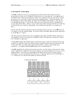
The operating principle is as follows: The Loop OUT of the standby receiver is connected to the Loop IN
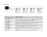
of the primary receiver (see “RX-4 Back Panel,” p. 6, for location of the loop connectors). If audio is
squelched on the primary receiver, then the signal from the standby is automatically routed through the
squelched channel. The loop will remain in effect until signal is once again detected on the primary
receiver; then the standby will cease routing its signal through.
For instance, suppose your EAS monitoring assignments consist of an AM station -- Receiver #1 -- and
the FM station to which Receiver #2 is tuned. By running a wire from Loop OUT of Receiver #3 (FM) to
Loop IN of Receiver #2, you would back up the primary FM assignment with the alternate FM station.
Furthermore, the individual receivers may be “daisy-chained,” that is, looped in a series of more than two
components. In a single RX-4 unit, for example, one could loop the OUT of Receiver #1 to the IN of
Receiver #2, then Receiver #2 to Receiver #3 in similar fashion, and finally, Receiver #3 to Receiver #4.
This arrangement would create a hot standby chain in which Receiver #4 is the primary, with Receiver #1
as the final standby component. If there is loss of signal in any or all of Receivers #2, 3, or 4, the output
channel of the failed receiver(s) will carry the audio coming in through its (or their) Loop IN. The source
of the audio to the non-receiving component(s) will be whichever receiver is the next functional unit up
the standby chain.
There is, however, one important exception to the loop feature as so far described: The AM receiver
cannot be looped through; in fact the Loop IN on the AM channel cannot be used (though AM Loop OUT
is fully functional). This situation arises from the general noisiness of the AM band, and the difficulty of
determining whether audio is truly squelched in order to trigger activation of the standby; AM loss-of-
signal simply cannot reliably be detected. In practical terms, this means that there is no hot standby for
the AM receiver (#1), though it can serve dependably as standby for any of the other receivers.
Содержание RX-4
Страница 1: ...RX 4 USER S MANUAL May 28 1997 Version 1 01 BURK Technology 7 Beaver Brook Road Littleton MA 01460 ...
Страница 2: ...RX 4 User s Manual Version 1 01 BURK Technology ...
Страница 4: ...RX 4 User s Manual Version 1 01 BURK Technology ii ...
Страница 11: ...13 Antenna Connector Female F type connector to ferrite core antenna via male F type connector ...
Страница 17: ...BURK Technology RX 4 User s Manual Version 1 01 13 ...
Страница 28: ...RX 4 User s Manual Version 1 01 BURK Technology 24 APPENDIX RX 4 SCHEMATICS ...
Страница 29: ...BURK Technology RX 4 User s Manual Version 1 01 25 ...
Страница 31: ......
Страница 32: ...RX 4 User s Manual Version 1 01 BURK Technology 4 ...
Страница 33: ...BURK Technology RX 4 User s Manual Version 1 01 5 ...
Страница 34: ...RX 4 User s Manual Version 1 01 BURK Technology 6 ...

