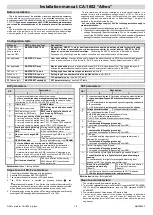
INSTALLATION TABLE OF CONTENTS
3
42
REQUIRED TOOLS
..........................................................................5
INSTALLATION CHECK LIST
...........................................................5
TECHNICAL ASSISTANCE
...............................................................6
BEFORE YOU BEGIN
.......................................................................6
PRECAUTIONS
............................................................................7-8
USING YOUR TEST PROBE
..............................................................8
MAKING WIRING CONNECTIONS
..............................................8-10
COMPONENTS
..............................................................................11
WIRING DIAGRAMS
................................................................11-12
H1 - 6-PIN HEAVY GAUGE WIRING CONNECTIONS
..................13-14
H1/1 Violet Wire Starter Output ..................................................13
H1/2-3 Red Wire +12V Power Input.............................................14
H1/4 Yellow Wire Ignition 1 Output..............................................14
H1/5 Pink Wire Ignition 2 Output.................................................14
H1/6 Brown Wire Accessory Output (Heater /ACC Output) ..............14
H2 - 5-PIN WIRE HARNESS
..........................................................15
H2/1 Red/White Wire Parking Light Relay Power Input ...................15
H2/2 White Wire Parking Light Relay Output .................................15
H2/3 Black Wire System Ground .................................................15
H2/4 Brown Wire (-) 200ma Horn Output .....................................15
H2/5 Red Wire System Power .....................................................15
H3 - BLACK 4-PIN CONNECTOR
FOR TWO-WAY TRANSCEIVER/ANTENNA MODULE
...........15-16
H4 - 9-PIN BLACK WIRE HARNESS
..........................................16-18
H4/1 Violet/White Wire Tach Input Connection..............................16
H4/2 Thin Black Wire - (-) Neutral Safety Switch or .........................17
(-) Remote Toggle Switch Input
H4/3 Brown/Red wire (+)
Positive Safety Shut Down Brake or Handbrake...........................17
H4/4 Grey wire (-) Negative Safety Shut Down ........................17-18
For Hood Pin Switch
H4/5 Red/White Wire - (-) 200mA Channel 3 Trunk Output ...............18
H4/6 Brown/Black Wire - (-) 200mA Factory Security Rearm Signal/
Key Sensor Output..................................................................18
Factory Security Rearm Signal Output
Ground Output During Start (Crank)
H4/7 Black/White Wire - (-) 200mA Dome Light Supervision Output...18
D200O/IM 6/05
Engine Starting
Engine Running
Your engine is starting
Your vehicles engine is
by remote control.
running in remote start mode.
Timer Control Start
Vibration Mode
Engine will start automatically
Remote vibrates when the
the same time the or every 2
system is triggered.
to 3 hours.
Low Battery
Driver paging /
Your must replace the battery
Lost and Found
in the remote control.
Someone is paging you
from your vehicle.
LCD REMOTE CONTROL TRANSCEIVER
THE REMOTE LCD ICON DESCRIPTION CHART :
Door Lock
Door Unlock
Your vehicle doors are locked.
Your vehicle doors are
unlocked.
Remote Transmission
In-Range Indicator
You are transmitting the signal
The system is within the
to the control unit.
remote control range.
Содержание DELUXE 200
Страница 1: ......


