6
KEY COMPONENTS
Main Frame
The Main frame of the girth welder is constructed of structural steel and square tube members. The slide square
tube mechanism with locking pins and pin holes is used to adjust the frame height for welding different sizes
of shell plates. The main frame of the girth welder is designed to support 550 lbs (250 kg) of weight, or enough
for two operators
.
The frame contains two serrated hardened steel flanged drive wheels manually adjusted to ride tank diameters
down to a minimum of 15’ (4.5 m.) The distance between wheel flanges is 1.8’’ (45mm) [standard] to accommodate
the shell wall thickness.
The machine frame is equipped with a hand railed operator platform with seat, a ladder provides a means for
operator to climb to the roof and access to the electric flux winch and separator tank for flux refill.
Guide wheel assembly at the lower end of the frame to simplify loading and
unloading the machine on the tank. Canvas curtains offer arc and operator
protection in windy conditions.
dual Motor drive
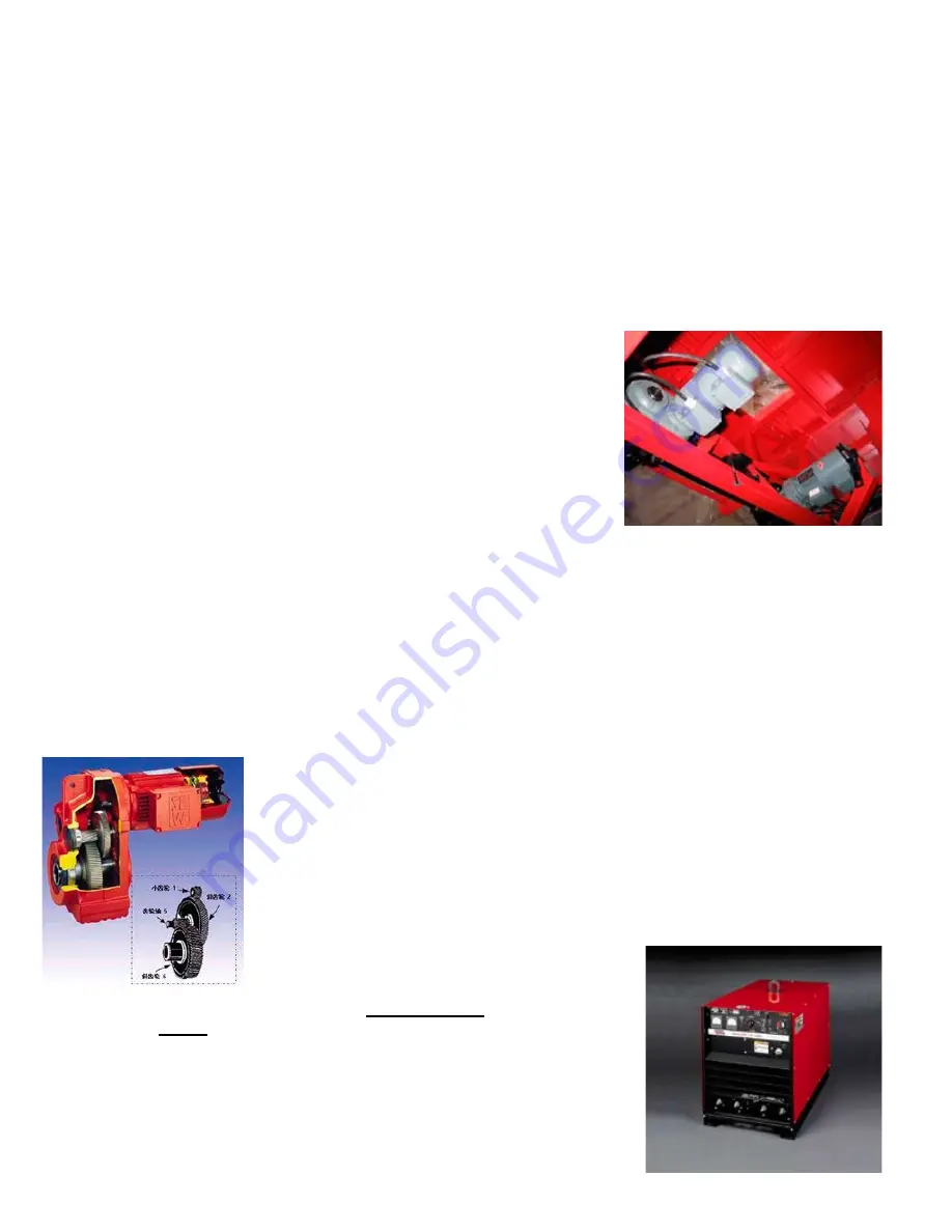
Each single flanged drive wheel is driven by an individual SAW motor /
reducer to provide extra tracking force to prevent slipping that could cause
weld defects. Drive motors are enclosed inside the frame top section with
aluminum panel for good weather protection.
Speeds for both motors are electronically synchronized and governed by an
inverter for accurate speed travel.
AC inverter:
1. Single-phase 220VAC input voltage
2. Automatic lift in torsion, 150% lift torsion in 6Hz.
3. Fully programmed & calibrated in factory
4. Soft PWM, running in low noise
5. 15 speed, PID, 4-20 MA input
6. Provides RS-485 communication
Caution: all the inverter drives inside the BGW control are pre-programmed before the girth welder is deliv-
ered to users on site. Please consult factory if re-programming is required.
The SEW motors and reducer requires minimal maintenance with advantages of
low noise & vibration, with 96% high efficiency through the reducer. It consists of
a high rigid housing and spur gear; all parts are precisely machined with minimum
tolerance for accurate travel mechanism.
Welding Gear
The standard welding equipment supplied is the Lincoln USA NA3 control and weld
head fitted with nozzle, wire feed rolls, wire straightener, and 50lbs (23Kg) wire reels
for feeding up to 3.2 mm (1/8’’) diameter wire.
Lincoln USA DC600 is the standard power supply
for the girth welder. Standard input power is 380V/3ph/50Hz and the line power
requirement is
40kVA. Other voltages and frequencies are available, please
consult factory for details.
Please refer to Lincoln’s NA3 and DC600 Instruction manuals for more informa-
tion on their welding equipment.
Power supplies are installed on a steel storage case with the electrical cabinet
for weather protection.
Содержание BGW-1000
Страница 25: ...25 CONTROL BOX ASSEMBLY EXPLODED VIEW ...
Страница 27: ...27 BGW 1087 GUIDE WHEEL ASSEMBLY EXPLODED VIEW 9 76 248 mm ...
Страница 28: ...28 OPERATIONS SCHEMATIC ...
Страница 29: ...29 WIRING DIAGRAM ...


