BS-GU2005P
Package Contents
Quick Setup Guide
BS-GU2005P......................................................................... 1
AC adapter............................................................................ 1
AC cable................................................................................. 1
Power cable retaining band .............................................. 1
Rubber feet........................................................................... 4
Serial number label............................................................. 2
- Keep the warranty statement at hand to request covered
repairs.
- Unless clearly permitted in the product documentation,
do not use other accessories (such as cables) with this
product other than those included in the package.
Notes:
- Do not install the switch on a place that is not stable.
- Do not place any objects that generate heat, such as another switch, on
this product.
- Wire cables not to get your legs hung up on them.
- Do not block the switch’s holes with any other devices or walls.
- Use the attached AC adapter and power cable. Using another AC
adapter or power cable may crash the switch or incite a fire disaster.
Warranty statement ............................................................. 1
Quick setup guide ................................................................ 1
Screws for 19 inch rack
(For Japan only; not usable for US/Canada users) ......... 4
Japanese manuals (For Japan only) .........................1 each
Diagrams and Layout
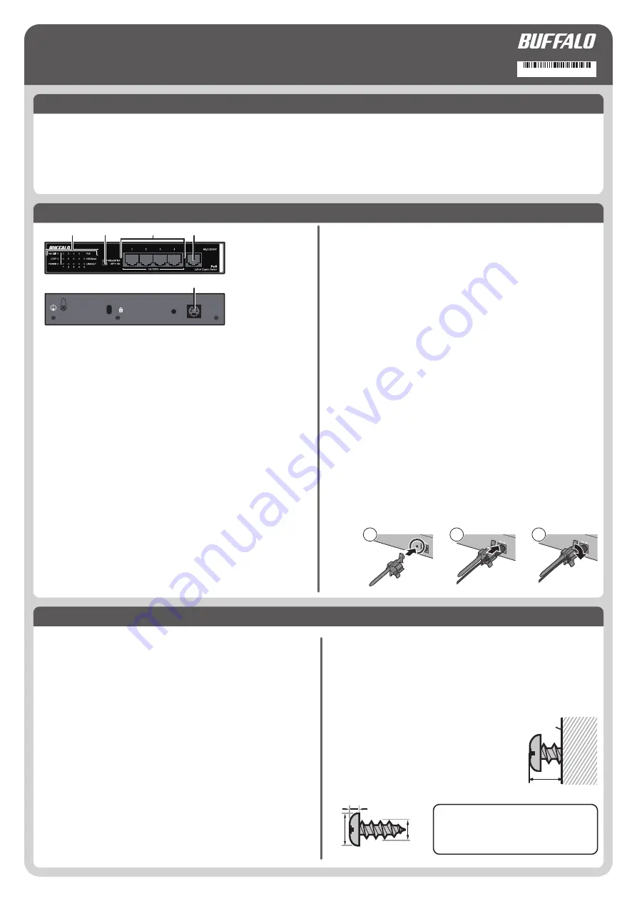
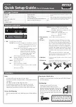
3. PoE ports
These Ethernet ports support PoE. Connect devices that
need Ethernet power to these ports. Each port can supply
up to 15.4 watts. The maximum total supply for all 6 ports
varies according to the operating temperature. If it is below
45°C (113°F), 50 watts. If it is above 45°C (113°F), 30 watts.
Connect Ethernet devices to the switch in ascending order of
port number. If the maximum total power for PoE exceeds 50
watts, power to ports will be disabled in descending order by
port number until the total output power for PoE is below 50
watts.
All ports support autonegotiation. The optimal duplex
mode (full duplex or half duplex) and transfer speed (1000,
100, or 10 Mbps) are selected automatically.
4. Uplink port
Connect other hubs or switches to this port. This port doesn't
support PoE.
2. Loop prevention
switch
Switches enable or disable loop prevention.
1. LEDs
Each LED indicates the following:
PoE LIMIT
On (amber): PoE is supplying more than 30 watts of power to
all devices. For temperatures above 45°C (113°F),
don't connect devices that draw more than 30
watts of PoE power total.
Blinking (amber): PoE power has been disabled to some ports
because the maximum 50 watts of PoE
power was exceeded. PoE power was
disabled for ports in order of descending
port number until the total PoE output
power was less than 50 watts.
Off: PoE feeding less than 30 W or PoE power is disabled
LOOP
Blinking (red): Blinks every second when a loop is blocked
Off: Working without loop
POWER
On (green): Power is on
Off: Power is off
PoE
On (green): PoE power is available
On (amber): Overcurrent, excessive power draw or any other
error
Off: PoE power is disabled
5. DC connector
Connect the included AC adapter to this connector. Secure
the AC adapter cable with the included cable retainer.
Floor or Shelf Mounting
Attach the supplied rubber feet to the bottom corners of the unit before
use.
Wall Mounting
To mount the unit to a wall, use 2 screws
(not included) with the dimensions shown
below. Screws should be installed 110 mm (4.33 in.)
apart. The screw head should project out from the
wall at 3 mm (0.12 in.) as the picture on the right.
Slide the mounting holes on the base of the switch
over them.
2
3
φ6
1000Mbps
On (green): 1000 Mbps link is established
Blinking (green): Loop prevention is working
Off: 100Mbps/10Mbps link is established or no link
LINK/ACT
On (green): Link is established
Blinking (green): Transmitting data or loop
prevention is working
Off: Link is not established
1
2
3
Mounting to a Metal Surface
To mount to a metal surface on a steel desk, use the "BS-MGK-A Magnet
Kit" (sold separately).
Do NOT use the screws included
in this product. These screws are
not designed for wall mounting.
(For US/Canada Users)
Installation
Wall
Max.3 mm
1
2
3
4
5
35020906-01


