background image

1-18

2003 Buell XB9S: Maintenance

HOME

BRAKE PEDAL ADJUSTMENT

1

WARNING

1

WARNING

After completing repairs or bleeding the system, always
test motorcycle brakes at low speed. If brakes are not
operating properly or braking efficiency is poor, testing
at high speeds could result in death or serious injury.

Check rear brake pedal operation:

Before every ride.

At the 1000 mile (1600 km) service interval.

At every 5000 mile (8000 km) service interval thereafter.

NOTE

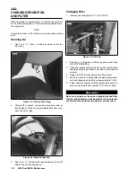
See 

Figure 1-11.

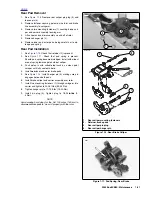
 On the very end of the threaded brake

rod, are two flat sides (2). To ensure proper thread
engagement with the clevis (3), the flat sides must
extend below the extruded nut (1) in the clevis by at least
one full thread. This is the minimum rod engagement. 

Also, there should be a minimum of 0.030 in. (0.8 mm)
between brake rod end and brake pedal.

1

WARNING

1

WARNING

Threaded rod should not be adjusted to the point of con-
tacting brake pedal. Improper adjustment could result in
death or serious injury.

1.

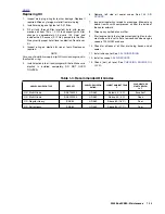
See 

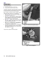
Figure 1-12. 

Inspect for minimum and maximum

brake rod engagement in brake clevis (4). Adjust as
required.

2.

Adjust brake pedal.

a. See 

Figure 1-12. 

Loosen locknut (3) while holding

rod adjuster (2). Move locknut away from top surface
of clevis (4).

b. Turn 

rod adjuster to set pedal height.

c.  Return locknut (3) to fit flush against top surface of

clevis and tighten to 130-173.5 in-lbs  (14.7-19.6
Nm).

NOTE

Brake pedal has no free play adjustment.

Figure 1-11. Critical Measurements with Typical 

Brake Pedal

Figure 1-12. Rear Brake Pedal Pushrod Adjustment

Minimum

Engagement

b0615x1x

1.

Extruded nut

2.

Flat sides (on the end of the threaded brake rod)

3.

Clevis

3

2

1

8349

1.

Bottom of master cylinder

2.

Rod adjuster

3.

Locknut

4.

Clevis

5.

Clevis pin

1

3

2

5

4

Содержание 2003XB9S

Страница 1: ... in the appropriate PARTS CATALOG Safety Safety is always the most important consideration when per forming any job Be sure you have a complete understanding of the task to be performed Use common sense Use the proper tools Protect yourself and bystanders with approved eye protection Don t just do the job do the job safely Removing Parts Always consider the weight of a part when lifting Use a hois...

Страница 2: ...ures for removing and installing bearings Bearings do not usually need to be removed Only remove bearings if necessary Bushings Do not remove a bushing unless damaged excessively worn or loose in its bore Press out bushings that must be replaced When pressing or driving bushings be sure to apply pressure in line with the bushing bore Use a bearing bushing driver or a bar with a smooth flat end Nev...

Страница 3: ...ing hardened wire unless they were designed for that purpose Always cut at right angles Don t use any prybar as a chisel punch or hammer Hammers Never strike one hammer against a hardened object such as another hammer Always grasp a hammer handle firmly close to the end Strike the object with the full face of the hammer Never work with a hammer which has a loose head Discard hammer if face is chip...

Страница 4: ...s Replace sockets showing cracks or wear Keep sockets clean Always use approved eye protection when using power or impact sockets Storage Units Don t open more than one loaded drawer at a time Close each drawer before opening up another Close lids and lock drawers and doors before moving storage units Don t pull on a tool cabinet push it in front of you Set the brakes on the locking casters after ...

Страница 5: ... motorcy cle will run normally using this type of gas You may find that some gasoline blends adversely affect the starting driveability or fuel efficiency of your bike If you expe rience one or more of these problems we recommend you try a different brand of gasoline or gasoline with a higher octane rating ENGINE OIL Use the proper grade of oil for the lowest temperature expected before the next o...

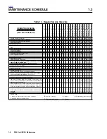
Страница 6: ...tch cable A A A A A A A A A A A Check rear belt and idler pulley Replace belt and idler pulley every 15 000 mi 24 000 km I I I R I I R I I R I Check front and rear tire pressure and inspect tread I I I I I I I I I I I I I I I I I I I I I Inspect front wheel bearings I I I I I I I I I I Inspect rear wheel bearings I I I I I Clean oil cooler fins X X X X X X X X X X X Change front fork oil X X X X X...

Страница 7: ...Dry with a clean chamois or soft dry natural fiber cloth Cleaning Between Washings Untreated molded in color body panels sometimes have a static charge that attracts dust Applying Harley Gloss or Har ley Glaze Polish and Sealant to molded in color surfaces will eliminate this condition To keep a high gloss finish on molded in color panels between washings 1 Spray Harley Gloss onto surface and wipe...

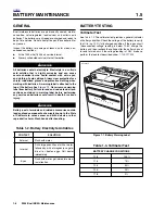
Страница 8: ...Test See Table 1 3 The voltmeter test provides a general indicator of battery condition Check the voltage of the battery to verify that it is in a 100 fully charged condition If the open circuit disconnected voltage reading is below 12 6V charge the battery and then recheck the voltage after the battery has set for one to two hours If the voltage reading is 12 8V or above perform the load test des...

Страница 9: ... that the battery has been frozen overheated or overcharged 6 Inspect the battery case for cracks or leaks STORAGE 1WARNING 1WARNING Always store batteries where they cannot be reached by children Contact with the battery s sulfuric acid could result in death or serious injury CAUTION The electrolyte in a discharged battery will freeze if exposed to freezing temperatures Freezing may crack the bat...

Страница 10: ...njury CAUTION Overtightening fasteners can damage battery terminals 3 Insert fastener through battery positive cable red into threaded hole of battery positive terminal and tighten fastener to 72 96 in lbs 8 11 Nm 4 Install terminal cover boot 5 Insert fastener through battery negative cable black into threaded hole of battery negative terminal and tighten fastener to 72 96 in lbs 8 11 Nm 6 Apply ...

Страница 11: ...y that there are no oil leaks from the oil filter and oil lines prior to operating the motorcycle Perform a hot check of the engine oil level at each fuel stop CAUTION Do not allow hot oil level to fall below lower mark on dip stick To do so may result in equipment damage and or malfunction CAUTION Do not overfill oil tank Overfilling oil tank may result in oil carryover to the air cleaner equipme...

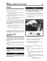
Страница 12: ...ring See 2 34 CHIN FAIRING 2 See Figure 1 6 Remove oil filter using pliers or belt type OIL FILTER WRENCH 3 Clean filter gasket contact surface on crankcase Surface should be smooth and free of any debris or old gasket material 4 Apply a thin film of clean engine oil to filter gasket 5 Pour 4 0 ounces 0 12 liter of clean engine oil into new fil ter when changing oil until filter is approximately 1...

Страница 13: ...ely DO NOT OVER TIGHTEN 6 Remove left side oil cooler scoop See 2 36 AIR SCOOPS 7 Inspect oil cooler fins for debris or damage Blow out any debris from fins with compressed air from the inside of the cooler outward 8 Wipe up any spilled oil on muffler 9 Start engine Verify that oil pressure signal light on instru ment support turns off after a few seconds when engine speed is 1000 RPM or above 10 ...

Страница 14: ... on the reservoir cap Mixing different types of fluid may adversely affect braking ability and lead to brake failure which could result in death or seri ous injury 1WARNING 1WARNING Use only fresh uncontaminated D O T 4 fluid Cans of fluid that have been opened may have been contami nated by moisture in the air or dirt Use of contaminated brake fluid may adversely affect braking ability and lead t...

Страница 15: ...ting bolts Warped rotor Replace brake pads Replace rotor and bushings as set Tighten bolts Replace rotor and bushings as set Ineffective brake lever pedal travels to limit Low fluid level Piston cup not functioning Fill master cylinder with approved brake fluid and bleed system Rebuild cylinder Ineffective brake lever pedal travel normal Distorted or glazed rotor Distorted glazed or contaminated b...

Страница 16: ...LUID to master cylinder reser voir Bring fluid level to within 1 8 in 3 2 mm of molded boss inside front master cylinder NOTE Do not reuse brake fluid 5 Slowly depress and release hand lever several times to build up hydraulic pressure then hold brake hand lever in the depressed position 6 While holding brake hand lever in the depressed posi tion open bleeder valve about 1 2 turn counterclockwise ...

Страница 17: ...r with motorcycle upright not on sidestand Bring fluid level between upper and lower marks on reservoir NOTE Do not reuse brake fluid 4 Slowly depress and release brake pedal several times to build up hydraulic pressure then hold brake pedal in the depressed position 5 While holding brake pedal in the depressed position open bleeder valve about 1 2 turn counterclockwise Brake fluid will flow from ...

Страница 18: ...of 0 030 in 0 8 mm between brake rod end and brake pedal 1WARNING 1WARNING Threaded rod should not be adjusted to the point of con tacting brake pedal Improper adjustment could result in death or serious injury 1 See Figure 1 12 Inspect for minimum and maximum brake rod engagement in brake clevis 4 Adjust as required 2 Adjust brake pedal a See Figure 1 12 Loosen locknut 3 while holding rod adjuste...

Страница 19: ...riction mate rial surface BRAKE ROTOR THICKNESS 1WARNING 1WARNING Do not allow brake fluid bearing grease lubricants etc to contact brake rotor when servicing motorcycle or reduced braking ability will occur which could result in death or serious injury See Figure 1 14 Check brake rotors for minimum thickness At the 1000 mile 1600 km service interval At every 2500 miles 4000 km service interval th...

Страница 20: ...on 1 Push pistons in with suitable tool such as a clean paint scraper until fully seated in bores Be careful not to dam age rotor 2 Install new inner pad from left side of motorcycle 3 Install new outer pad from right side of motorcycle 4 See Figure 1 15 Install pin 2 making sure it engages hole on both pads and spring clip 5 Rotate caliper clockwise to align mounting fastener hole 6 See Figure 1 ...

Страница 21: ...ring towards piston side of caliper 3 Push piston in with suitable tool such as a clean paint scraper until fully seated in bore 4 Install new inner and outer brake pads 5 See Figure 1 16 Install hanger pin 4 making sure pin engages hole on both pads 6 Install brake caliper and carrier assembly over rotor 7 Install two mounting fasteners 1 through swingarm into carrier and tighten to 24 26 ft lbs ...

Страница 22: ...r indicator bars become visible on the tread sur faces 2 Tire cords or fabric become visible through cracked side walls snags or deep cuts 3 A bump bulge or split in the tire 4 Puncture cut or other damage to the tire that cannot be repaired WHEEL BEARINGS 1WARNING 1WARNING Never use compressed air to spin dry bearings Very high bearing speeds can damage unlubricated bearings Spinning bearings wit...

Страница 23: ...steners and washers from clutch inspec tion cover Remove clutch inspection cover with gasket from primary cover CAUTION Do not overfill the transmission with fluid Overfilling may cause rough clutch engagement and incomplete dis engagement clutch drag and or difficulty finding neutral at engine idle 5 See Figure 1 21 Add SPORT TRANS FLUID Part No 98854 96 quart size Part No 98855 96 gallon size as...

Страница 24: ...o shorten cable housing until there is a large amount of free play at clutch hand lever 3 See Figure 1 19 Remove three fasteners and washers from clutch inspection cover Remove clutch inspection cover and gasket from primary cover 4 See Figure 1 23 Remove spring 1 and lockplate 2 Using a flat tip screwdriver turn adjusting screw 3 counterclockwise until it lightly bottoms 5 Turn adjusting screw cl...

Страница 25: ...away from bracket Gap between ferrule and bracket should be 1 16 1 8 in 1 6 3 2 mm b See Figure 1 22 Set free play by turning adjuster 4 c Tighten jam nut 3 against adjuster 4 d Slide boot 1 over cable adjuster mechanism 7 Change or add transmission fluid if necessary 8 See Figure 1 19 Install clutch inspection cover and gas ket using three fasteners and washers and tighten to 84 108 in lbs 10 12 ...

Страница 26: ... and leaves a visible mark it is cutting the bare aluminum A knife point will not penetrate the chrome plating 3 Replace rear sprocket if major tooth damage or loss of chrome exists Drive Belt See Figure 1 25 Inspect drive belt for Cuts or unusual wear patterns on both sides of belt Outside edge bevelling 8 Some bevelling is common but it indicates that sprockets are misaligned Outside surface for...

Страница 27: ...N CONDITION REQUIRED ACTION 1 Internal tooth cracks hairline OK to run but monitor condition 2 External tooth cracks Replace belt 3 Missing teeth Replace belt 4 Chipping not serious OK to run but monitor condition 5 Fuzzy edge cord OK to run but monitor condition 6 Hook wear Replace belt 7 Stone damage Replace belt if damage is on the edge 8 Bevel wear outboard edge only OK to run but monitor cond...

Страница 28: ...1 28 2003 Buell XB9S Maintenance HOME NOTES ...

Отзывы: