5
Fitting
Logalux LTN/LTD/LTH/LF 400...3000 – 6 720 818 806 (2015/12)
12
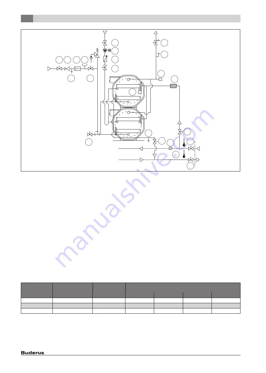
Fig. 7
Connection diagram for hydraulic connection with 2 water heaters
AW
DHW outlet
EK
Cold water inlet
EZ
DHW circulation inlet
[1]
Diaphragm safety valve, component-tested in accordance
with DIN 4753-1 (1 piece per cylinder, if these can be shut
off individually)
[2]
Drain valve
[3]
Shut-off device
[4]
Air vent valve
[5]
Shut-off valve with drain valve
[6]
DHW circulation pump with timer
[7]
Non-return valve
[8]
Pressure reducer; if the line pressure is higher than 80 % of
the response pressure of the pressure relief valve
[9]
Test valve
[10]
Non-return component
[11]
Pressure gauge connector in accordance with DIN 4753-1
< 1000 litres cylinder capacity; pressure gauge in
accordance with DIN 4753-1 > 1000 litres cylinder capacity
[12]
Tee and drain valve (important for quicker flushing/draining)
[13]
Temperature sensor; high limit safety cut-out with flow
temperature > 110 °C
[14]
Temperature sensor for temperature controller
[17]
Water filter
[18]
Setting element
[19]
Thermometers
[1...19]
All parts provided by the customer.
Pressure relief valve (provided by the customer)
▶ Attach a notice with the following text to the pressure relief valve:
"Never close the discharge pipe. Water may escape for safety
reasons during heating."
▶ Design the cross section of the discharge pipe in such a way, that it at
least matches the outlet cross section of the pressure relief valve
(
▶ Test the standby status of the pressure relief valve from time to time
by venting it.
Checking for leaks
▶ Check all connections and the cover of the inspection aperture for leaks.
6 720 817 906-05.1T
13
1
17
19
18
VHF
RHF
2
3
3
12
8 10 11
9
14
4
5
3
6
7
3
AW
EZ
EK
3
3
3
3
Connection diameter
at least
Rated content of the
water vessel
Maximum
heat output
1)
1) Output information in accordance with DIN 4708 in the case of Tv = 80 °C or steam positive pressure = 1 bar. Observe the relevant max. heating output for other flow
temperatures and steam pressures.
Series
I
kW
LT...N
LT...H
LT...D
LF
DN20
200...1000
150
400...950
400...550
DN25
1000...5000
250
1500
750...950
400...1500
400...950
DN32
> 5000
1000
2000...3000
1500...3000
2000...3000
1500...3000
Table 8 Sizing the discharge pipe
Содержание Logalux LTD950
Страница 24: ......


