BTECH BETTER BY DESIGN BT7373 Скачать руководство пользователя страница 2

2

INSTALLATION SAFETY INSTRUCTIONS

 CAUTION: This mount is intended for use only with the maximum weights 
indicated. Use with flat screens heavier than the maximum indicated may 
result in instability causing possible injury. 


Do not attempt to install this product until all instructions and warnings have been read and 
properly understood. Please keep these instructions for future reference. 
B-Tech International Limited, its distributors and dealers are not liable or responsible for 
damage or injury caused by improper installation, improper use or failure to observe these 
safety instructions. In such cases, all guarantees will expire. 
 

General 

 
Great care must always be taken during installation as most AV equipment is of a fragile 
nature, possibly heavy and easily damaged if dropped. 
If you do not fully understand the instructions or are not sure how to install this product safely, 
then please consult a professional for advice and/or to install this product for you. Failure to 
mount this product correctly may cause serious injury or death both during installation and at 
any time thereafter. 
Do not mount any AV equipment that exceeds the specific weight limit of the product you are 
installing. This weight limit will be clearly stated on each product and its packaging and will 
vary from product to product. 
 

Product location 

 
Please pay careful attention to where this product is located. Some locations are not suitable 
for installation. 
If located in a public or frequently populated area ensure that the product is out of the 
immediate reach of people.  
 

Fixing hardware 

 
It is highly recommended that all fixing screws be used where supplied and that the purpose of 
all other fixing hardware is fully understood. In some cases more AV equipment fixing 
hardware will be supplied to accommodate different models of equipment and set up 
configurations. 
The installer must be satisfied that any supplied fixing hardware is suitable for each specific 
installation. If any fixing screws or included hardware are deemed not sufficient for a safe 
installation then please consult a professional or your local hardware store. 
 

Hazard limitation 

 
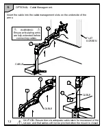
When routing cables take advantage of any built in cable management features that the 
product might provide and ensure that all cables are tidy and secure. Check to see that any 
moving aspect of the product can do so unhindered by any cabling. 
Some products have moving parts and the potential to cause injury through the crushing or 
trapping of fingers or other body parts. 
Particular attention to the nature of moving parts is required especially when assembling 
installing and adjusting during set up. 
Immediately after installations double-check that the work done is safe and secure. Double-
check all necessary fixings are present and are of ample tightness. 
It is recommended that periodic inspections of the product and its fixing points are made as 
frequently as possible to ensure that safety is maintained. If in doubt consult a professional AV 
installer or other suitably qualified person. 
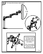
The articulating arm may spring upward and may cause injury or damage to the equipment 
when the monitor is removed. Secure the arm by lifting the arm to highest position, to remove 
monitor safely.  
 

Содержание BETTER BY DESIGN BT7373

Страница 1: ...6 Product Dimensions 15 B Tech Contact Details 16 PLEASE KEEP THIS FOR FUTURE REFERENCE 2 5mm Hex Key Supplied 4mm Hex Key Supplied Designed for screens up to 24 61cm 9kg 20lbs Fits screens with VESA mounting patterns 75 x 75mm and 100 x 100mm Optional desk clamp and grommet included Easy tilt adjustment 40 tilt Maximum extension is 457mm 18 Features three swivel points 360 at pole 360 at both piv...

Страница 2: ...uct is out of the immediate reach of people Fixing hardware It is highly recommended that all fixing screws be used where supplied and that the purpose of all other fixing hardware is fully understood In some cases more AV equipment fixing hardware will be supplied to accommodate different models of equipment and set up configurations The installer must be satisfied that any supplied fixing hardwa...

Страница 3: ......

Страница 4: ...BT7373 PARTS LIST 4 Suitable for loads up to 9kg 20lbs GROMMET CLAMP 1 2 2 9 9 10 10 3 4 5 6 7 8 11 12 13 11 14 13 6 16 15 18 22 23 21 20 23 22 ...

Страница 5: ...RUB SCREW 2 11 M6 x 8mm HEX SCREW 5 12 M10 E RING 1 13 M10 METAL WASHER 2 14 M10 NUT 1 15 GROMMET PLATE 1 16 LONG HANDWHEEL 1 17 CABLE CLIP 1 18 CIRCULAR FOAM PAD 2 19 RECTANGULAR FOAM PAD 2 20 FLAT PLASTIC CAP 1 21 ANGLED PLASTIC CAP 1 22 M6 x 10mm SCREW 2 23 M6 METAL WASHER 2 24 CABLE TIE 5 25 2 5mm HEX KEY FOR PART10 1 26 4mm HEX KEY FOR PARTS 9 11 1 INTERFACE KIT A M4 x 12mm SCREW 4 B M4 x 30m...

Страница 6: ...6 INSTALLATION INSTRUCTIONS 1 Choose a preferred mounting method i Clamp page 6 ii Grommet page 8 i Desk clamp option Max 70mm 2 8 4 11 18 5 7 11 8 13 6 12 19 ...

Страница 7: ...7 Attach the foam pads to the underside of the clamp base Place the mount over edge of the desk and tighten the short handwheel 18 DESKTOP 6 4 8 19 ...

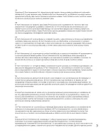
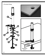
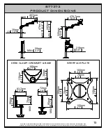
Страница 8: ...8 ii Grommet Clamp Max 95mm 3 7 4 15 18 6 13 14 16 11 19 ...

Страница 9: ...grommet plate Then attach the foam pads onto the grommet plate Place the mount over the cable management hole and screw the handwheel into the grommet plate then tighten the nut to clamp the desk 26 26 5 15 11 11 4 4 18 4 16 DESKTOP 16 14 19 ...

Страница 10: ... To lock the adjustment collar hold the top of the collar and rotate the lower part of the adjustment collar Attach the interface plate to the flat screen FLAT SCREEN TOP BOTTOM LOCK COLLAR D C B A 1 2 E 3 4 ...

Страница 11: ...11 4 Slide the flat screen and arms onto the pole adjust height then tighten the grub screw FLAT SCREEN UNLOCK COLLAR LOCK COLLAR i ii iii 2 3 4 3 3 10 25 ...

Страница 12: ...movement of the screen and that cables will not be pinched when the mount is closed Insert the cable into the cable management slots on the underside of the arms FLAT SCREEN WARNING Ensure articulating arms are fully extended before connecting cables CABLE 2 2 2 2 CABLE CABLE 17 4 ...

Страница 13: ... To increase tilt resistance tighten part 9 26 9 If this does not hold the screen at the required tilt remove the flat screen from the interface Then remove plastic nut cover and tighten the M8 nyloc nut 40 ...

Страница 14: ...14 7 Tilt and swivel 360 90 360 360 25 10 10 25 26 9 9 26 ...

Страница 15: ...Y OF THE INFORMATION CONTAINED IN THIS DOCUMENT 100mm 3 9 75mm 3 75mm 3 100mm 3 9 120mm 4 7 120mm 4 7 83 7mm 3 3 95mm 3 7 70mm 2 8 MAX DESK CLAMP GROMMET BASE INTERFACE PLATE 169mm 6 7 110mm 4 3 30mm 1 2 476 7mm 18 8 325mm 12 8 59mm 2 3 MIN 218mm 8 6 457mm 18 MAX 35mm 1 4 O 478mm 18 8 MAX 243mm 9 6 MIN 72mm 2 8 95mm 3 7 MAX ...

Страница 16: ...ett Technologies Limited All other brands and product names are trademarks of their respective owners Photographs are for illustrative purposes only E OE EUROPE Brixtonlaan 32 Zaventem 1930 Brussels Belgium Email info btechproav com ASIA PACIFIC Ruby Industrial Complex Singapore 347740 Email info btechavmounts com sg NORTH AMERICA 203 Eggert Road Buffalo NY 14215 USA Email info btechavmounts com C...

Отзывы: