


6
© BTB Auto Glass & Body Shop Tools
2. Cut-Out Guidelines & Examples
2.1 Blade Types, Blade Usage, Blade Depth
Control
Details of BTB's full product range can be found in our dedicated
Removal System catalogue supplied with the power tool, and
available for viewing or downloading from BTBTOOLS.COM.
A training video can also be viewed from this website.
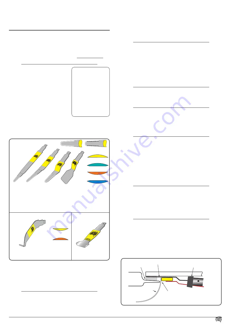
2.1.1 SIX BASIC BLADE TYPES
• Standard Straight Blades
• Standard Bent Blades
• Standard "Z" Blades
• Standard Spade "Z" Blades
• Powered Cold Knife Blades
• Winged Scraper Blades
Variations of these include:
• Length up to 375 mm
• Flexibility of blade tip
• Serrated or Non-Serrated
• Cutting Tip Length of PCK blades
• Wing Width of Scraper Blades
• Cutting Tip Profile (
designated by colour, see below
)
serrated
GREEN 'V'
ORANGE 'R'
YELLOW
BLUE 'VR'
straight
bent
Z style
spade
Yellow
or
Green
blades have the flat side of their cutting tip down.
Green
'V' blades are a safety edge version of the yellow blades
Orange
or
Blue
(reverse) blades have the flat side of their cutting
tip up (bent opposite to Yellow and Green blades).
Blue
'V' blades
are a safety edge version of the orange blades.
ORANGE 'R'
YELLOW
Powered Cold Knife (PCK) Blades Winged Pinchweld
Scraper Blades
Yellow
blades have the flat side of their
cutting tip up.
Orange
blades have the
flat side of their cutting tip down.
Radius grind of cutting
tip won't scratch
vehicle paintwork.
non-serrated
Standard Blades
Diagram D
2.1.1.1 STANDARD NON-SERRATED AND SERRATED BLADES
Non-Serrated
blades can be used in all glass and panel applications.
Serrated
blades are optional and can provide a faster more
aggressive cutting action.
2.1.2 Fitting and Changing Blades in the Power Tool
To fit blades, always turn power switch to the OFF (right) position
or disconnect the power cord. Using the 4.0mm
WKKEY
Allen key
provided, unscrew the
SPB33
cone point retaining screw (located
Refer to Diagram A
on page 2 and Section
2.2 on
page 7
to plan
your cut out.
Refer to Hints, Tips and
Operating Techniques
on
page
14
for further
blade use guidelines.
A full blade list can be
found on
page
15
.
via the hole in the controller cap) two full rotations counter
clockwise. Insert the blade as far as it will go into the chuck and
firmly re-tighten retaining screw in clockwise motion. Check that
the blade is securely held before reconnecting or turning on power.
NOTE:
All blades will also fit in the WK7 and WK7L manual handles.
2.1.3 Sharpening Blades
The best cutting results are obtained with sharp blades. The
procedure for sharpening the blades is as follows:
1. Sharpen blades from radiused (rounded) side only.
2. Keep flat side of blade smooth to allow sliding motion on the
glass surface.
WARNING:
COARSE GRINDING OR BLUNT BLADES WILL SERIOUSLY
REDUCE PERFORMANCE, EFFICIENCY AND SAFETY.
2.1.4 Replace Worn Blades
If shape / length of blade tip reduces from repeated sharpening, or
is varied from its original shape, replace blade to regain efficiency.
2.1.5 Cutting Lubricant is Important
Using Cutting lubrication is important for blade movement. Always
spray both the inside and the outside of the glass where possible.
Use water or a cutting lubricant / additive mixed with water that has
been
approved
by your adhesive manufacturer.
2.1.6 Blade Vibration When Cutting Internally
If a blade vibrates or flaps against the glass, the operator is doing
something wrong. Refer to the following points 1, 2 and 3 below
and also
Diagrams J, K
and
Diagram L
.
1. Check blade tip is flat against the glass or panel.
2. Ensure blade and tool are held firm, the angle is correct, and the
controller cap is against the glass.
3. When cutting below dashboard with long blade, keep tool and
blade in straight line. See
Diagram L
and
Diagram M
.
2.1.7 Protect Glass and Painted Panel Surfaces
As an extra precaution to avoid scratching the glass with the back
of the cutting blade, you can apply a small Velcro® pad (supplied
in kits) to the offending section of the blade. Ensure the blade is
dry. The
WK11PP
paint protector controller arm can be used in
conjunction with external Powered Cold Knife blades.
2.1.8 Rest the Nylon Controller Cap Against the Glass
The nylon controller cap will not scratch glass or panel and is to
be held against the glass surface for internal cutting. This also
guarantees efficient cutting and operator control because the blade
and cutting tip is held at the correct angle and hugging the glass
surface. It is also designed to attach blade cutting depth controller
arms. See also
2.1.9 Adjustable Cutting Depth Controller Arms (page 7).
WK11BW5 CONTROLLER ARM
WHEEL STOPS AT PILLAR TRIM
INTERIOR ROOF LINER
OR PILLAR TRIM
CAR
BODY
Z BLADE
GLASS
NYLON CONTROLLER CAP
RESTS AGAINST GLASS SURFACE
ADHESIVE
Diagram E


