background image

2 6

9.0

Outputs Menu

Name

The first screen in the Output menu is the Name function. Here you can

identify each output with a name suitable  to its function, selecting from a list

of names in the FDS-355, such as SUB, or 2” HORN.
Turn the parameter wheel to select the desired name. If the name selected

while stereo is NOT linked begins with L<space> or R<space>, then the L or

R will not be displayed when stereo linking is on.
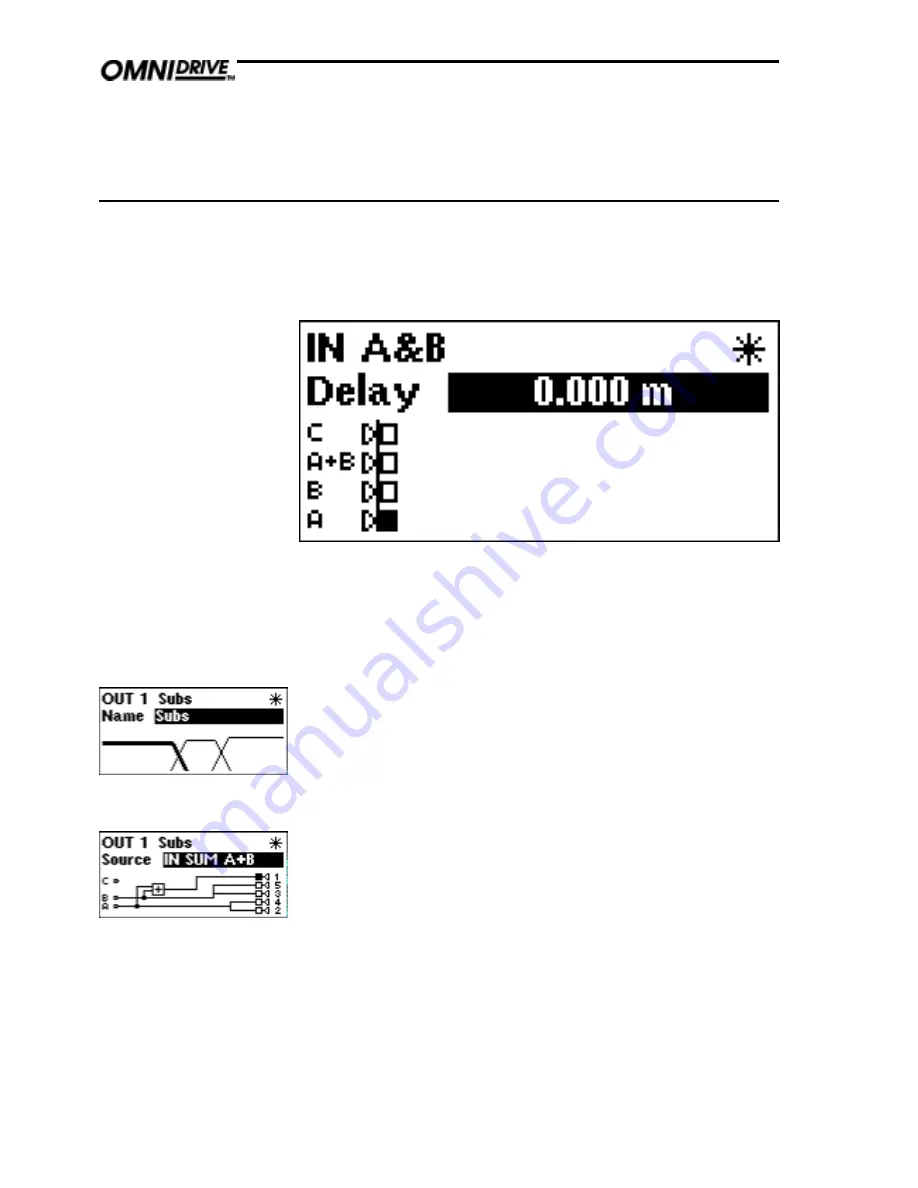
Source

This screen gives a graphical representation of the input to output assignment

matrix. The channel selected has its speaker icon highlighted, and a

connecting line shows to which input it is currently assigned. The input source

name is also shown above the diagram.
Note that the diagram shows straight through connections from inputs to

outputs, omitting any internal processing (EQ, Xover etc) for clarity.
To change the source input, turn the parameter wheel until the speaker icon is

connected to the desired source.

Note: The speaker icons are not drawn in a fixed order. The diagram will be

drawn in the clearest way, to avoid lines crossing on the screen. Therefore

care must be taken when changing input to output assignments, as the

numbers next to the speaker icons (representing the outputs) will change

positions.

Outputs menu

To select any one of the 5 output bands, press the parameter wheel until the

output is shown on the screen, and the EDIT led above the desired channel

illuminates. Pushing and holding the encoder, then pressing a mute button,

will take the display to the corresponding output channel.

Содержание FDS 355

Страница 1: ...1 FDS 355 User Manual...

Страница 2: ...rbance EU EN61000 3 2 1995 Electrical Safety EU EN60065 1993 Radiated Emissions USA FCC part 15 Class B Electrical Safety USA UL813 ETL 1996 Commercial Audio Equipment Electrical Safety CAN UL813 ETLc...

Страница 3: ...king 9 3 0 Mechanical Installation 10 4 0 Mains Power Connection 11 4 1 Mains power 11 5 0 Controls 12 5 1 Input section 12 5 2 Output section 14 5 3 Rear panel 15 Screen Layout 16 6 0 Default Screen...

Страница 4: ...37 15 2 Keep relative delays while delaying a group 37 15 3 Name a band 37 15 4 Make a band full range 37 15 5 Add EQ for Constant Directivity horns 38 15 6 Loading custom logos 38 16 0 PC Card 39 16...

Страница 5: ...e Recalling a program from a PC Card To load a file from a PC card push the card into the slot on the front panel of the FDS 355 Press RECALL Push the DOWN key to highlight Int and turn the encoder to...

Страница 6: ...an be delayed as one using the delay link facility Adding EQ Use the UP DOWN keys to move to the EQ screen The EQ shape can be edited first The shape of the EQ can be selected from one of the followin...

Страница 7: ...s of closely spaced crossover filters can be significant Phase compensation helps you to keep the response of the system with the minimum of fiddle factor adjustments Headroom Management System H M S...

Страница 8: ...to optimise the performance of the output converters This ensures that the D A is always operating at full range minimising converter noise whatever the system operating level All the system operatin...

Страница 9: ...onnected to all exposed metal surfaces Any rack framework into which this unit may be mounted is assumed to be connected to the same grounding circuit The incoming mains power is fused within the FDS...

Страница 10: ...s advisable to support the unit at the rear and or sides to lessen the stress on the front mounting flange The necessary support can generally be bought ready built as a rack tray As with any low leve...

Страница 11: ...ed in accordance with the following code 4 1 Mains power The wire which is coloured Green and Yellow or Green must be connected to the terminal which is marked with the letter E or by the Earth signal...

Страница 12: ...call mode E Main Display The main LCD screen displays current parameters being edited with numerical and graphical representations When the user is not editing the screen can display the overall syste...

Страница 13: ...e which combination of input channels are being edited The Card LED underneath illuminates when a PC Card is inserted into the front panel slot Note If all three input LEDs illuminate at once which is...

Страница 14: ...e mute status of the output band D Mute key Pressing a mute key will toggle the associated band output on and off The mute LED is illuminated when the output is MUTED Mute status is saved when a progr...

Страница 15: ...ch provides an easy way to upload new software D MIDI interface connectors E 5 Band outputs The FDS 355 audio outputs are electronically balanced and floating Transformer balancing is available as a r...

Страница 16: ...1 6 Screen layout Overview...

Страница 17: ...wheel in will return you to the default screen after a few seconds Pushing and holding the encoder then pressing a mute button will take the display to the corresponding output channel Use the UP and...

Страница 18: ...tilities menu will enter Inputs Mode Here the parameters of each input can be adjusted The delay screen shows the delay value set for each input Refer to section 8 0 Inputs menu The next screen allows...

Страница 19: ...ts simultaneously Refer to section 9 0 Outputs menu The Xover screens allow each edge of the crossover point to be adjusted using the following parameters Polarity Phase Low and Hi Filter shape and Lo...

Страница 20: ...he main area of the screen contains the three output band curves Each band curve represents the frequency response of the high and pass crossover rolloffs in addition to any equalisation filters that...

Страница 21: ...and anticlockwise selects OFF The Configuration facility defines the general operating mode for the FDS 355 either Mono or Dual Stereo 2 Way Stereo The parameter wheel is used to select the desired co...

Страница 22: ...The limit units screen allows the units of limiter threshold to be changed between dBu and mV depending on your amplifier specification Limit units The Lock Out mode prevents access to editing functio...

Страница 23: ...system manufacturers to lock the unit so that certain parameters cannot be viewed and edited OEM lock is the highest level of security of the unit and can lock out any parameter of the unit To enter...

Страница 24: ...ms values to be stored with the program The 355 adds the front panel value to the band gain value for each output Therefore when recalling a program the unit will warn to set ALL front panel trim valu...

Страница 25: ...eter wheel will set the amount of delay required on the input This delay is typically used to set the delay for delay towers etc or to stagger the delays between the left and right channels to move so...

Страница 26: ...shown above the diagram Note that the diagram shows straight through connections from inputs to outputs omitting any internal processing EQ Xover etc for clarity To change the source input turn the p...

Страница 27: ...se will increase the frequency to the final clockwise position OFF which mutes the output Phase The phase relationship of the two band edges at the crossover point can be adjusted in 5 degree steps us...

Страница 28: ...its are dBu but can be changed to mV Refer to section 7 0 Utilities menu for details on how to change this BSS Audio recommends setting the limiter thresholds below the amplifier clipping sensitivity...

Страница 29: ...l automatically convert the value of the delay if delay units is changed from distance to f p s in the utility menu and vice versa This also allows fine tuning once a value has been set in frames Turn...

Страница 30: ...t EQ must be edited Another EQ assuming there are spare EQs will then be inserted automatically A dotted contour shows the effect of the crossover filters on this band NOTE The A B signal is mixed aft...

Страница 31: ...tween 15Hz and 16kHz Cut Boost Turn the parameter wheel clockwise to add boost gain or anti clockwise for cut gain Cut boost is available between 15dB and 15dB in 0 2dB increments Turning the paramete...

Страница 32: ...pe at the top of the screen While the Program number is highlighted turning the parameter wheel will cycle through programs 1 60 While each of the letters in the Program name are highlighted turning t...

Страница 33: ...nal and the current program STORE TYPE Once the program name has been entered the store type selected and the Program lock status cleared pressing the STORE key again will prompt the message STORE UNL...

Страница 34: ...ill acoustically combine to a flat amplitude response The main lobe of the polar response will also be on axis When more filters are added to the crossover for more than two drivers however the crosso...

Страница 35: ...zone distribution system without using any of its crossover facilities Using this mode a common input signal can be routed to up to 5 separate outputs each with delays EQ and limiters Typical uses for...

Страница 36: ...vide a full 5 way system It can also function as a 4 way system fed from input A with an independent sub bass output fed from input C or B Two FDS 355s working in this mode can form a stereo 5 way sys...

Страница 37: ...use the UP key to cycle through the screens until the Delay Link screen is shown Turning the parameter wheel will show all possible choices which are determined by the bands sourced from the same inp...

Страница 38: ...e EQ Frequency and adjust the freq by turning the parameter wheel to show a frequency of about 2kHz check with your manufacturer for detailed information about Frequency and Boost requirements for a s...

Страница 39: ...re the first byte on a disc The format writes a DOS boot sector with basic format data but does not write boot software This is followed by a single File Allocation Table FAT starting at byte 200H The...

Страница 40: ...nyone who knows how to operate the FDS 355 17 3 Owner lock The Owner lock mode gives the user the privilege of being able to hide selected parameters from other users view and prevent those parameters...

Страница 41: ...is BSS for OEM lock The use of a default password is to prevent accidental or malicious setting of lock flags The user enters the password by turning the parameter wheel to change each letter and eit...

Страница 42: ...anged by people who know the OEM Lock password Be warned that it is impossible to unlock a unit where the password has been forgotten 17 5 Safe The FDS 355 has a hidden function called SAFE SAFE mode...

Страница 43: ...ution The unit is clipping internally Reduce EQ or gain Problem A new program will not save over an existing program Solution Check that the existing program is not locked If it is clear the key icon...

Страница 44: ...ed in the European Union you may as an alternative return the unit to any other BSS distributor in the European Union You should include a statement listing the faults found The unit s serial number m...

Страница 45: ...nputs Electronically balanced floating Transformer balanced option InputImpedance 10k Maximum Input Level 20dBu balanced Outputs Electronically balanced floating Transformer balanced option Maximum Ou...

Страница 46: ...y Link output 28 Delete program 24 Down Key 12 E Edit LED 14 Encoder 12 EQ 30 adding a new EQ 30 Cut Boost 31 frequency 31 lock extra 40 41 shape 30 width 31 EQ screens 18 EQ shape 30 F File Allocatio...

Страница 47: ...27 Compensation 34 Polarity 28 Power AC Fusing 9 connection 11 inlet 15 Program files 39 Q Quick reference 5 adding EQ for CD Horns 38 Keeping relative delays 37 Making a band full range 37 Naming a...

Страница 48: ...menu 18 MIDI channel 22 MIDI dump 24 MIDI mode 22 OEM Lock 23 Owner Lock 23 Xover mode 23 V Voltage setting 9 W Warranty info 44 Width EQ 31 Wiring convention 15 X Xover adjust 23 Output High freq 27...

Страница 49: ...49 User Notes...

Страница 50: ...5 0 User Notes...

Страница 51: ...51...

Страница 52: ...5 2 User Notes...

Отзывы: