background image


Installation instruction 


Motor-driven blocking 

device EasyBlocker 

108320 


VdS - Class C 

G 196 089 
G 197 051 


108320Err_ENG.doc 

version 6.0a / 06.04.2016 

page 1 

Содержание EasyBlocker 108320

Страница 1: ...Installation instruction Motor driven blocking device EasyBlocker 108320 VdS Class C G 196 089 G 197 051 108320Err_ENG doc version 6 0a 06 04 2016 page 1 ...

Страница 2: ...ctuation with dynamic signals 8 2 2 3 Actuating with a static signal 9 2 2 4 Switching on several blocking devices 10 2 3 Magnetic contact and door monitoring 12 2 4 Commissioning 12 3 MALFUNCTIONS 13 3 1 Electrical emergency opening 14 3 2 Mechanic emergency opening 14 3 3 Replace the bolt 15 4 TECHNICAL DATA 16 5 DRILLING TEMPLATE 17 Installation instruction Motor driven blocking device EasyBloc...

Страница 3: ...02 with magnetic contact 10 m cable 108320 22 with magnetic contact 10 m cable 108320 1 without magnetic contact 3 5 m cable 108320 3 without magnetic contact 3 5 m cable 108320 12 without magnetic contact 10 m cable 108320 32 without magnetic contact 10 m cable 1 2 Mechanic assembly Safety Due to the robust assembly made of plastic and stainless steel a high reliability and durability of more tha...

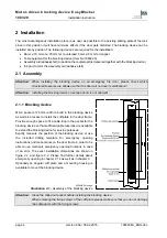
Страница 4: ...ice Mill a pocket of 20 mm width to build in the blocking device as well as a recess to install the cuff plate in the door frame Provide enough space to fit a cable loop in the pocket for the blocking device so that sufficient cable reserves are available to extend the blocking device for service purposes Exactly measure the position of the blocking device or use the included drilling template for...

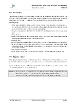
Страница 5: ...en the door 6 On the door leaf you will recognize a color circle which shows the exact position of the counterpart 7 Mark the center using a center punch and drill the hole according to the dimensions of the counterpart Please find the installation dimensions of the counterpart on the technical data sheet also refer to chapter 4 8 Assemble the counterpart 9 Close the door and perform a functional ...

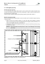
Страница 6: ...le to use the mechanic emergency opening in case of an error Mark the hole for the emergency opening on the door frame after having installed the blocking device in the door frame by means of the drilling template for emergency opening instructions or by means of the installation dimensions on illustration 2 2 If appropriate drill the hole for emergency opening ø 6 mm into the door frame and close...

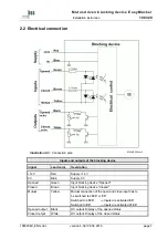
Страница 7: ...Blue Supply 0 V Opened Green Input blocking device Opened Closed Brown Input blocking device Closed Mutual Yellow Mutual connection of the open and close input has to be switched to 12 V or 0 V Switched to 12 V Inputs are activated 0 V Switched to 0 V Inputs are activated 12 V Opened output Black OC output Display of the opened status Closed output White OC output Display of the closed status 1083...

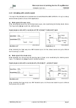
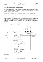
Страница 8: ...cal emergency opening in chapter 3 1 2 2 2 Actuation with dynamic signals These are timely limited impulses for the open and close actuations which are also used to actuate bistable door openers For the impulse length the following values need to be observed Impulse length 50 ms for the standard versions 200 ms for the battery versions The impulse is saved in the blocking device and the closing or...

Страница 9: ...tivated signal Illustration 2 7 8320AB207en tif Illustration 2 8 8320AB208en tif When controlling the Open entry via a PNP transistor upon 12V the mutual needs to be put on 0 V and the Closed entry on 12 V B Static signal at the closed entry When activating the Closed entry the blocking device closes when deactivating the blocking device opens The Opened entry always needs to be switched active Si...

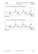
Страница 10: ... after another it is possible to cascade the blocking devices The outputs Closed output or Opened output can be used for status display when switching on the LEDs On the battery version the Closed output and the Opened output are implemented as impulse outputs I e the outputs are controlled for 10 seconds after having opened or closed and then they switch off If the input signal changes within thi...

Страница 11: ...ction 108320 B Connect several blocking devices in series for standard version Illustration 2 12 8320AB212en tif C Connect several blocking devices in series for battery version Illustration 2 13 8320AB213en tif 108320Err_ENG doc version 6 0a 06 04 2016 page 11 ...

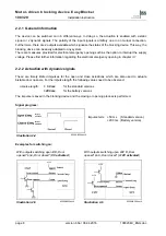
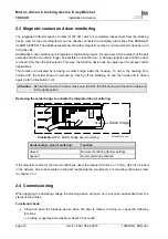
Страница 12: ...e solder bridge is removed by sucking off the soldering tin and the housing lid is closed again refer to illustration 2 14 Attention Before the housing is closed make sure the bolt the bolt spring and the motor cable are in the right position Removing the solder bridge to activate the integrated door monitoring Illustration 2 14 Solder bridge door monitoring 8320AB214en eps Solder bridge door moni...

Страница 13: ...d output is activated again for 10 seconds Until version V1 3 to June 2013 the output active time was 0 5 seconds and was activated on every bolt position check every 68 seconds Attention Battery version If the Closed entry is actuated with a static signal the Closed output is activated every 10 seconds Î because of higher current consumption at rest on state Closed the battery version of the bloc...

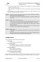
Страница 14: ...ixture the bolt will retract due to an integrated spring mechanism The motor can be shifted out of its fixture from both sides of the door To do so please proceed as follows 1 Drill a hole of ø 6 mm at the positions which had been marked on the door frame when mounting or just remove the cover cap on the door frame if the emergency opening hole had already been applied during assembly Attention Do...

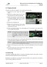
Страница 15: ... cuff plate When the power supply is switched on the bolt will automatically be moved in the position Open 7 Please check that all parts are in correct position bolt spring bolt motor and motor cable Close the housing lid again and tighten it by using the screws Attention Before the housing is closed make sure the motor cable lies correctly in the proper duct and cannot be damaged by the housing l...

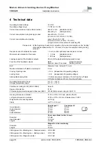
Страница 16: ... 8 mm bolt path 11 5 mm Maximum distance cuff plate to counterpart 8 mm Closing Opening time 0 5 s independent of operating voltage Locking force 5 N independent of operating voltage Admissible shearing force 1 0 kN at a maximum distance of 5 mm from the cuff plate 0 75 kN at a distance of 8 mm from the cuff plate Operating temperature range Storage temperature range 25 C 60 C 40 C 70 C Climates a...

Страница 17: ...tion Drilling templates on a scale of 1 1 Please copy this page and cut out the drilling templates 8320AB51en eps 8320AB52en eps Illustration 5 1 Drilling template emergency opening Illustration 5 2 Hole ø6 mm depending on the position of the cable entry point Drilling template A or B to be performed at point A or B Magnet position at the door leaf ...

Отзывы: