26
Dirty Sensor Test Using an SD-TRK4
1. Turn the key switch to the RESET/TEST position for two
seconds.
2. Verify that the test/reset station’s Trouble LED flashes.
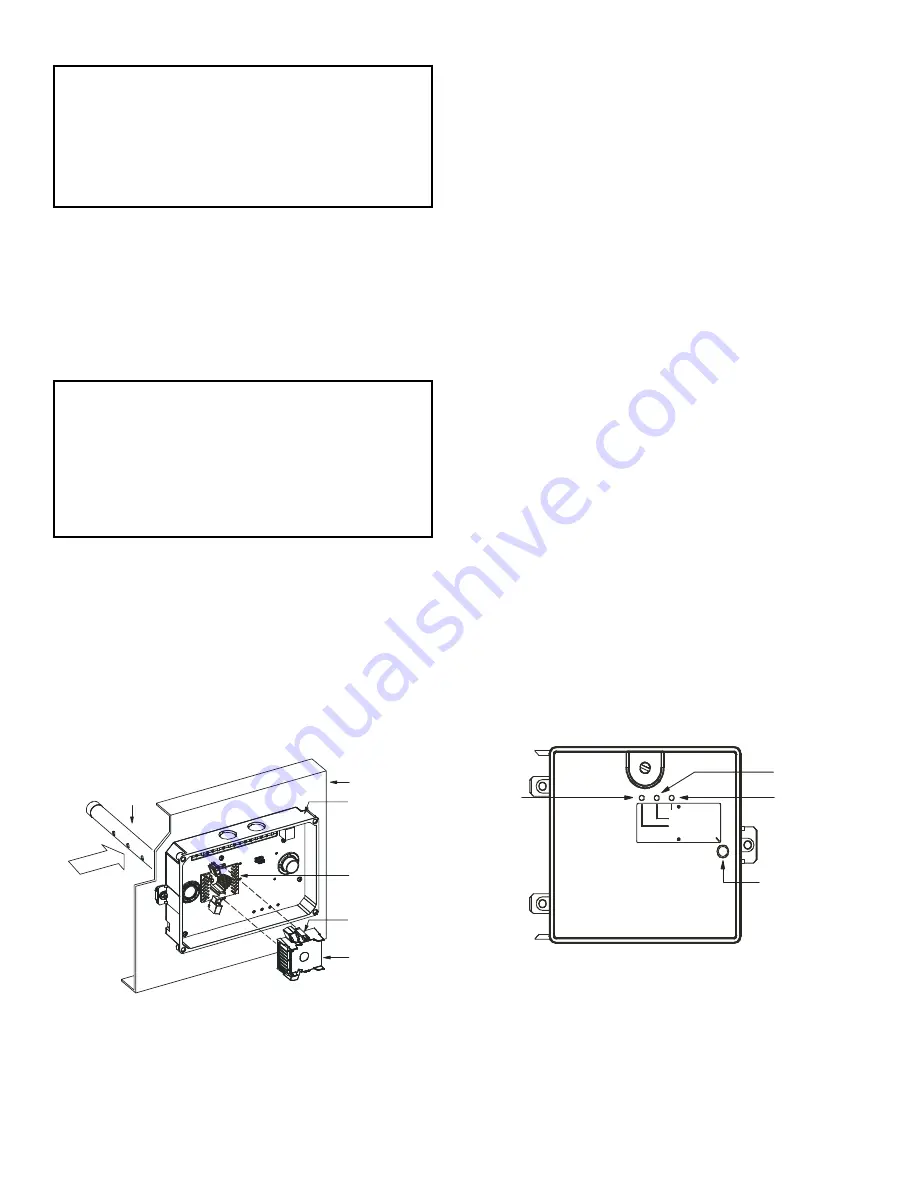
Detector Cleaning
CLEANING THE SMOKE DETECTOR
Clean the duct smoke sensor when the Dirty LED is flashing
continuously or sooner if conditions warrant.
1. Disconnect power from the duct detector, then remove the
sensor’s cover (see Fig. 44).
2. Using a vacuum cleaner, clean compressed air, or a soft
bristle brush, remove loose dirt and debris from inside the
sensor housing and cover. Use isopropyl alcohol and a
lint-free cloth to remove dirt and other contaminants from
the gasket on the sensor’s cover.
3. Squeeze the retainer clips on both sides of the optic housing.
4. Lift the housing away from the printed circuit board.
5. Gently remove dirt and debris from around the optic plate
and inside the optic housing.
6. Replace the optic housing and sensor cover.
7. Connect power to the duct detector, then perform a sensor
alarm test.
Fig. 44 — Sensor Cleaning Diagram
Indicators
NORMAL STATE
The smoke detector operates in the normal state in the absence
of any trouble conditions and when its sensing chamber is free
of smoke. In the normal state, the Power LED on both the sen-
sor and the controller are on and all other LEDs are off.
ALARM STATE
The smoke detector enters the alarm state when the amount of
smoke particulate in the sensor’s sensing chamber exceeds the
alarm threshold value. (See Table 8.) Upon entering the alarm
state:
• The sensor’s Alarm LED and the controller’s Alarm LED
turn on.
• The contacts on the controller’s two auxiliary relays switch
positions.
• The contacts on the controller’s alarm initiation relay
close.
• The controller’s remote alarm LED output is activated
(turned on).
• The controller’s high impedance multiple fan shutdown
control line is pulled to ground Trouble state.
The SuperDuct smoke detector enters the trouble state under
the following conditions:
• A sensor’s cover is removed and 20 minutes pass before it
is properly secured.
• A sensor’s environmental compensation limit is reached
(100% dirty).
• A wiring fault between a sensor and the controller is detected.
An internal sensor fault is detected upon entering the trouble
state:
• The contacts on the controller’s supervisory relay switch
positions (see Fig. 45).
• If a sensor detects trouble, the sensor’s Trouble LED the
controller’s Trouble LED turns on.
• If 100% dirty, the sensor’s Dirty LED turns on and the
controller’s Trouble LED flashes continuously.
• If there is a wiring fault between a sensor and the control-
ler, the controller’s Trouble LED turns on, but not the sen-
sor’s LED.
Fig. 45 — Controller Assembly
NOTE: All troubles are latched by the duct smoke detector. The
trouble condition must be cleared and then the duct smoke detec-
tor must be reset in order to restore it to the normal state.
IMPORTANT: OPERATIONAL TEST ALERT
Failure to follow this ALERT can result in an unnecessary
evacuation of the facility.
Holding the test magnet against the sensor housing for
more than seven seconds will put the duct detector into the
alarm state and activate all automatic alarm responses.
IMPORTANT: OPERATIONAL TEST ALERT
Failure to follow this ALERT can result in an unnecessary
evacuation of the facility.
If the smoke detector is connected to a fire alarm system,
first notify the proper authorities that the detector is under-
going maintenance, then disable the relevant circuit to
avoid generating a false alarm.
HVAC DUCT
SAMPLING
TUBE
RETAINER
CLIP
OPTIC
PLATE
OPTIC
HOUSING
SENSOR
HOUSING
AIRFLOW
ALARM
POWER
TEST/RESET
SWITCH
TROUBLE
RESET
ALARM
TROUBLE
POWER
Содержание Preferred 581J04-14
Страница 36: ...36 Fig 60 Integrated Gas Control IGC Board RED LED STATUS ...
Страница 44: ...44 Fig 65 RTU Open Overlay for Economizer Wiring ...
Страница 45: ...45 Fig 66 VFD Overlay for W2770 Controller Wiring ...
Страница 96: ...96 Fig B 581J 04 06 YAC Control Diagram 208 1 60 208 230 3 60 460 575 3 60 APPENDIX D WIRING DIAGRAMS ...
Страница 99: ...99 Fig E 581J 07A B C YAC Control Diagram 208 230 3 60 460 575 3 60 APPENDIX D WIRING DIAGRAMS ...
Страница 100: ...100 Fig F 581J 08 09 YAC Control Diagram 208 230 3 60 460 575 3 60 APPENDIX D WIRING DIAGRAMS ...
Страница 101: ...101 Fig G 581J 11YAC Control Diagram 208 230 3 60 460 575 3 60 APPENDIX D WIRING DIAGRAMS ...
Страница 102: ...102 Fig H 581J 12 YAC Control Diagram 208 230 3 60 460 575 3 60 APPENDIX D WIRING DIAGRAMS ...
Страница 103: ...103 Fig I 581J 04 06 YAC Power Diagram 208 230 1 60 APPENDIX D WIRING DIAGRAMS ...
Страница 104: ...104 Fig J 581J 04 06 YAC Power Diagram 208 230 3 60 460 3 60 APPENDIX D WIRING DIAGRAMS ...
Страница 105: ...105 Fig K 581J 04 06 YAC Power Diagram 575 3 60 APPENDIX D WIRING DIAGRAMS ...
Страница 106: ...106 Fig L 581J 07 12D F YAC Power Diagram 208 230 3 60 460 3 60 6 Ton 2 Stage with Cooling APPENDIX D WIRING DIAGRAMS ...
Страница 108: ...108 Fig N 581J 07 12A B C YAC Power Diagram 208 230 3 60 460 3 60 APPENDIX D WIRING DIAGRAMS ...
Страница 109: ...109 Fig O 581J 07 12A B C YAC Power Diagram 575 3 60 APPENDIX D WIRING DIAGRAMS ...
Страница 110: ...110 Fig P 581J 08 09 YAC Power Diagram 230 460 3 60 APPENDIX D WIRING DIAGRAMS ...
Страница 111: ...111 Fig Q 581J 08 09 YAC Power Diagram 575 3 60 APPENDIX D WIRING DIAGRAMS ...
Страница 112: ...112 Fig R 581J 11 YAC Power Diagram 208 230 3 60 APPENDIX D WIRING DIAGRAMS ...
Страница 113: ...113 Fig S 581J 11 YAC Power Diagram 460 3 60 APPENDIX D WIRING DIAGRAMS ...
Страница 114: ...114 Fig T 581J 11 YAC Power Diagram 575 3 60 APPENDIX D WIRING DIAGRAMS ...
Страница 115: ...115 Fig U 581J 12 YAC Power Diagram 230 460 3 60 APPENDIX D WIRING DIAGRAMS ...
Страница 116: ...116 Fig V 581J 12 YAC Power Diagram 575 3 60 APPENDIX D WIRING DIAGRAMS ...
Страница 117: ...117 Fig W 581J 14 YAC Control Diagram 208 230 3 60 460 575 3 60 APPENDIX D WIRING DIAGRAMS ...
Страница 118: ...118 Fig X 581J 14 YAC Power Diagram 208 230 3 60 APPENDIX D WIRING DIAGRAMS ...
Страница 119: ...119 Fig Y 581J 14 YAC Power Diagram 460 3 60 APPENDIX D WIRING DIAGRAMS ...
Страница 120: ...120 Fig Z 581J 14 YAC Power Diagram 575 3 60 APPENDIX D WIRING DIAGRAMS ...
Страница 121: ...121 Fig AA 581J 04 06 YAC Control Diagram 230 1 60 230 460 575 3 60 with Dehumidification APPENDIX D WIRING DIAGRAMS ...
Страница 122: ...122 Fig AB 581J 07A B C YAC Control Diagram 230 1 60 230 460 575 3 60 with Dehumidification APPENDIX D WIRING DIAGRAMS ...
Страница 123: ...123 Fig AC 581J 08 09 YAC Control Diagram 230 460 575 3 60 with Dehumidification APPENDIX D WIRING DIAGRAMS ...
Страница 124: ...124 Fig AD 581J 11 YAC Control Diagram 230 1 60 230 460 575 3 60 with Dehumidification APPENDIX D WIRING DIAGRAMS ...
Страница 125: ...125 Fig AE 581J 12 YAC Control Diagram 230 460 575 3 60 with Dehumidification APPENDIX D WIRING DIAGRAMS ...
Страница 126: ...126 Fig AF 581J 04 06 YAC Power Diagram 208 230 1 60 with Perfect Humidity System APPENDIX D WIRING DIAGRAMS ...
Страница 127: ...127 Fig AG 581J 04 06 YAC Power Diagram 230 460 3 60 with Perfect Humidity System APPENDIX D WIRING DIAGRAMS ...
Страница 128: ...128 Fig AH 581J 04 06 YAC Power Diagram 575 3 60 with Perfect Humidity System APPENDIX D WIRING DIAGRAMS ...
Страница 129: ...129 Fig AI 581J 07A B C YAC Power Diagram 230 460 3 60 with Perfect Humidity System APPENDIX D WIRING DIAGRAMS ...
Страница 130: ...130 Fig AJ 581J 07A B C YAC Power Diagram 575 3 60 with Perfect Humidity System APPENDIX D WIRING DIAGRAMS ...
Страница 131: ...131 Fig AK 581J 08 09 YAC Power Diagram 230 460 3 60 with Perfect Humidity System APPENDIX D WIRING DIAGRAMS ...
Страница 132: ...132 Fig AL 581J 08 09 YAC Power Diagram 575 3 60 with Perfect Humidity System APPENDIX D WIRING DIAGRAMS ...
Страница 133: ...133 Fig AM 581J 11 YAC Power Diagram 208 230 3 60 with Perfect Humidity System APPENDIX D WIRING DIAGRAMS ...
Страница 134: ...134 Fig AN 581J 11 YAC Power Diagram 460 3 60 with Perfect Humidity System APPENDIX D WIRING DIAGRAMS ...
Страница 135: ...135 Fig AO 581J 11 YAC Power Diagram 575 3 60 with Perfect Humidity System APPENDIX D WIRING DIAGRAMS ...
Страница 136: ...136 Fig AP 581J 12 YAC Power Diagram 230 460 3 60 with Perfect Humidity System APPENDIX D WIRING DIAGRAMS ...
Страница 137: ...137 Fig AQ 581J 12 YAC Power Diagram 575 3 60 with Perfect Humidity System APPENDIX D WIRING DIAGRAMS ...
Страница 138: ...138 Fig AR 581J 14 YAC Control Diagram 230 460 575 3 60 with Perfect Humidity System APPENDIX D WIRING DIAGRAMS ...
Страница 139: ...139 Fig AS 581J 14 YAC Power Diagram 208 230 3 60 with Perfect Humidity System APPENDIX D WIRING DIAGRAMS ...
Страница 140: ...140 Fig AT 581J 14 YAC Power Diagram 460 3 60 with Perfect Humidity System APPENDIX D WIRING DIAGRAMS ...
Страница 141: ...141 Fig AU 581J 14 YAC Power Diagram 575 3 60 with Perfect Humidity System APPENDIX D WIRING DIAGRAMS ...
Страница 142: ...142 Fig AV YAC Direct Digital System Control Wiring Diagram System 50HE500891 F APPENDIX D WIRING DIAGRAMS ...
Страница 143: ...143 Fig AW RTU Open Wiring Diagram APPENDIX D WIRING DIAGRAMS ...