background image

10

TechAssist

Diagnostics--at--a--Glance

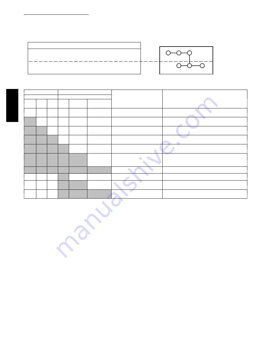
Single phase air conditioning units are equipped with a system diagnostics tool called the TechAssist

t

. Follow Table 4 to identify and

correct problems in system operation.

Table 4—

TechAssist

t

Diagnostics--at--a--Glance

LED

Description

ON

OFF

Y

Thermostat cooling call

Yes

No

. . . . . . . . . . .

. . . . . . . . .

. . . . . . . .

HPS

High Pressure Switch

Closed

Open

. . . . . . . .

. . . . . . . . . . .

. . . . .

LPS

Low Pressure Switch

Closed

Open

. . . . . . . . .

. . . . . . . . . . . .

. . . . .

230V

AC Line Power Available

Yes

No

. . . . . . . .

. . . . . . . . .

. . . . . . . .

Contactor

Contactor Energized

Yes

No

. . .

. . . . . . . . . . .

. . . . . . . .

Compressor Compressor Running

Yes

No

.

. . . . . . . . . . .

. . . . . . . .

Y

HPS

LPS

230V Contactor Compressor

CONTROL

POWER

Note: --- Follow arrows to first unlit LED in control (green) ladder or power (amber) ladder to determine problem area.

*** --- For contactor LED to be On, all control LEDs (green) as well as 230V LED (amber) must already be on, and contactor must operate . . . . .

properly

Control Ladder

Power ladder

Indication

Possible Cause & Quick

Trouble---Shooting

Green LEDs

Amber LEDs

Y

HPS LPS 230V Contac-

tor

Compressor

Off

Off

Off

Off

Off

Off

--- No 230V power to unit

--- No thermostat call

--- Check 230V disconnect/ circuit breaker

--- Check 230V L1 & L2 wire connections

On

Off

Off

--- ---

Off

Off

--- HPS Switch Open

--- Check pressures

--- Check HPS wire connections

On

On

Off

--- ---

Off

Off

--- LPS Switch Open

--- Check pressures

--- Check LPS wire connections

On

On

On

Off

Off

Off

--- No 230V power to unit

--- Check 230V disconnect / circuit breaker

--- Check 230V L1 & L2 wire connections

On

On

On

On

Off

Off

--- Contactor open ***

--- Check Contactor and replace if necessary

--- Check contactor wire connections

On

On

On

On

On

Off

--- Compressor not running*

--- Check for compressor protector trip, capacitor

fault, faulty connections or compressor fault.

SEE BELOW.

On

On

On

On

On

On

--- Compressor running

--- OK

Off

Off

Off

On

Off

Off

--- No thermostat call, standby --- OK

Off

Off

Off

On

On

Off

--- Contactor stuck closed,

compressor tripped

--- Check Contactor and replace if necessary

--- Check wire connections for shorts

Off

Off

Off

On

On

On

--- Contactor stuck closed,

compressor running

--- Check Contactor and replace if necessary

--- Check wire connections for shorts

*Compressor not running: If all LEDs are on except the Compressor, this indicates that power is applied to the compressor but it is not running. Check the

following sequence:

1) Check all compressor wire connections

2) Check run capacitor and replace if necessary

3) Try starting compressor

4) If compressor LED does not come on, then leave unit in standby for up to four hours to allow thermal protector to reset, and all pressures to equalize

5) Try starting the compressor again

6) If compressor LED comes on, then turns off quickly, investigate starting issues such as low line voltage

7) If compressor LED never comes on, compressor may be faulty.

123A

/124A

Содержание Legacy 123A

Страница 1: ...ECOMMENDATIONS 2 INSTALLATION 3 9 Step 1 Check Equipment Jobsite 3 Step 2 Install on Solid Pad 3 Step 3 Clearance Requirements 3 Step 4 Operating Ambient 3 Step 5 Install TXV 3 4 Step 6 Make Piping Connections 5 7 Step 7 Make Electrical Connections 7 8 Step 8 Compressor Crankcase Heater 8 Step 9 Install Electrical Accessories 8 Step 10 Start Up 9 Step 11 Check Charge 9 Step 12 Final Checks 9 TECH ...

Страница 2: ...ate at higher pressures than standard R 22 systems To avoid damage to the unit or possible personal injury do not use R 22 service equipment or components on Puron refrigerant equipment INSTALLATION RECOMMENDATIONS NOTE In some cases noise in the living area has been traced to gas pulsations from improper installation of equipment 1 Locate unit away from windows patios decks etc where unit operati...

Страница 3: ...t per compressor manufacturer specifications STEP 3 Clearance Requirements When installing allow sufficient space for airflow clearance wiring refrigerant piping and service Allow 30 in clearance to service end of unit and 48 in above unit For proper airflow a 6 in clearance on 1 side of unit and 12 in on all remaining sides must be maintained Maintain a distance of 24 in between units Position so...

Страница 4: ...lacing TXV on R 22 Indoor Coil 1 Pump system down to 2 psig and recover refrigerant 2 Remove coil access panel and fitting panel from front of cabinet 3 Remove TXV support clamp using a 5 16 in nut driver Save the clamp 4 Remove R 22 TXV using a backup wrench on flare connections to prevent damage to tubing 5 Using wire cutters cut equalizer tube off flush with vapor tube inside cabinet 6 Remove b...

Страница 5: ...ndition Rated tubing diameters shown in Table 1 recommended up to 80 ft See Product Data for acceptable alternate vapor diameters and associated capacity losses For tubing requirements beyond 80 ft substantial capacity and performance losses can occur Following the recommendations in the Longline Guideline Residential Split System Air Conditioners and Heat Pumps Using Puron Refrigerant will reduce...

Страница 6: ...id tube to the indoor coil 2 Wrap filter drier with damp cloth 3 Braze filter drier to above 5 liquid tube Flow arrow must point towards indoor coil 4 Connect and braze liquid refrigerant tube to the filter drier A05178 Fig 5 Liquid Line Filter Drier Refrigerant Tubing Connection Outdoor Connect vapor tube to fitting on outdoor unit vapor service valves see Table 1 Connect and braze the 3 8 coupli...

Страница 7: ...tdoor unit has not shifted during shipment Ensure tubes are not rubbing against each other or any sheet metal Pay close attention to feeder tubes making sure wire ties on feeder tubes are secure and tight STEP 7 Make Electrical Connections WARNING ELECTRICAL SHOCK HAZARD Failure to follow this warning could result in personal injury or death Do not supply power to unit with compressor terminal box...

Страница 8: ...ermostat is located more than 100 ft from unit as measured along the control voltage wires use No 16 AWG color coded wire to avoid excessive voltage drop All wiring must be NEC Class 1 and must be separated from incoming power leads Use furnace transformer fan coil transformer or accessory transformer for control power 24 v 40 va minimum NOTE Use of available 24 v accessories may exceed the minimu...

Страница 9: ...lower relay Compressor and motors stop If indoor unit is equipped with a time delay relay circuit the indoor blower will run an additional 90 sec to increase system efficiency STEP 11 Check Charge Unit Charge Factory charge and charging method are shown on unit information plate Charge Puron units with cylinder in inverted position and a commercial type metering device in manifold hose Charge refr...

Страница 10: ...ire connections On On On Off Off Off No 230V power to unit Check 230V disconnect circuit breaker Check 230V L1 L2 wire connections On On On On Off Off Contactor open Check Contactor and replace if necessary Check contactor wire connections On On On On On Off Compressor not running Check for compressor protector trip capacitor fault faulty connections or compressor fault SEE BELOW On On On On On On...

Страница 11: ... 78 76 74 72 70 68 266 80 78 76 74 72 70 274 82 80 78 76 74 72 283 84 82 80 78 76 74 291 86 84 82 80 78 76 299 88 86 84 82 80 78 308 90 88 86 84 82 80 317 92 90 88 86 84 82 326 94 92 90 88 86 84 335 96 94 92 90 88 86 345 98 96 94 92 90 88 354 100 98 96 94 92 90 364 102 100 98 96 94 92 374 104 102 100 98 96 94 384 106 104 102 100 98 96 395 108 106 104 102 100 98 406 110 108 106 104 102 100 416 112 ...

Страница 12: ... S Do not install a suction line filter drier in liquid line S POE oils absorb moisture rapidly Do not expose oil to atmosphere S POE oils may cause damage to certain plastics and roofing materials S Wrap all filter driers and service valves with wet cloth when brazing S A factory approved liquid line filter drier is required on every unit S Do NOT use an R 22 TXV S If indoor unit is equipped with...

Отзывы: