background image

935CA: Installation, Start-up, Operating and Service and Maintenance Instructions

Manufacturer reserves the right to change, at any time, specifications and designs without notice and without obligations.

22

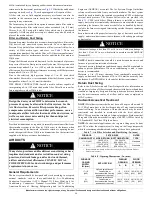
1.Nominal 350 CFM/ton cooling airflow is delivered with SW1-5 and SW4-3 set to OFF.

Set SW1-5 to ON for nominal 400 CFM/ton (+15% airflow).

Set SW4-3 to ON for nominal 325 CFM/ton (-7% airflow).

Set both SW1-5 and SW4-3 on ON for nominal 370 CFM/ton (+7% airflow).

The above adjustments in airflow are subject to motor horsepower range/capacity

This applies to Cooling and Low-Cooling airflow, but does not affect continuous fan airflow.

2.Maximum cooling airflow is achieved when switches SW2-3, SW2-2, SW2-1 and SW1-5 are set to ON, and SW4-3 is set to OFF.

3.All heating CFM's are when comfort/efficiency adjustment switch (SW1-4) is set to OFF

4.Ductwork must be sized for high-heating CFM within the operational range of ESP. Operation within the blank areas of the chart is not recommended because heat operation will be above

1.0 ESP.

5.All airflows on noted 21" (533 mm) casing size furnaces are 5% less on side return only installations.

6.Side returns for noted models, require two sides, or a side and bottom to allow sufficient airflow at the return of the furnace.

7.Airflows over 1800 CFM require bottom return, two-side return, or bottom and a side return or excessive watt draw may result. A minimum filter size of 20 x 25” (508  x 635 mm) is

required.

COOLING

4

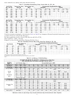
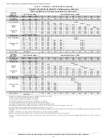
 AND HEATING AIR DELIVERY - CFM (Bottom Return With Filter)

(SW1-5 and SW4-3 set to OFF, except as indicated. See notes 1 and 2)

Unit Size: 

30080C21


5

Clg/CF Switch settings

External Static Pressure (ESP)

Clg Switches:

SW2-3

SW2-2

SW2-1

0.1

0.2

0.3

0.4

0.5

0.6

0.7

0.8

0.9

1.0

Clg Default:

OFF

OFF

OFF

1825

1830

1830

1825

1825

1825

1815

1810

1805

1785

CF Switches

SW3-3

SW3-2

SW3-1

Low-Clg Default:

OFF

OFF

ON

695

700

Note 4

Cooling 

(SW2)

Low-Cooling 

(SW3)

OFF

ON

OFF

870

885

880

880

Note 4

OFF

ON

ON

1045

1060

1070

1070

1070

1070

Note 4

ON

OFF

OFF

1310

1315

1315

1315

1310

1300

1290

1280

Note 4

ON

OFF

ON

1470

1475

1480

1480

1480

1475

1465

1460

1450

1440

ON

ON

OFF

1825

1830

1830

1825

1825

1825

1815

1810

1805

1785

ON

ON

ON

2170

2180

2180

2175

2170

2150

2080

1995

1915

1825

Maximum Clg Airflow

2

2230

2225

2235

2230

2195

2165

2110

2020

1935

1845

CF Switches

SW3-3

SW3-2

SW3-1

Cont. Fan Default:

OFF

OFF

OFF

695

700

Note 4

Continuous Fan 

(SW3)

OFF

OFF

ON

695

700

Note 4

OFF

ON

OFF

870

885

880

880

Note 4

OFF

ON

ON

870

885

880

880

Note 4

ON

OFF

OFF

870

885

880

880

Note 4

ON

OFF

ON

870

885

880

880

Note 4

ON

ON

OFF

870

885

880

880

Note 4

ON

ON

ON

870

885

880

880

Note 4

Heating (SW1)

Heat Airflow

3

1425

1430

1435

1435

1435

1425

1420

1410

1400

1390

Unit Size:

66100C21

6

Clg/CF Switch settings

External Static Pressure (ESP)

Clg Switches:

SW2-3

SW2-2

SW2-1

0.1

0.2

0.3

0.4

0.5

0.6

0.7

0.8

0.9

1.0

Clg Default:

OFF

OFF

OFF

1765

1775

1790

1805

1810

1820

1820

1820

1820

1820

CF Switches

SW3-3

SW3-2

SW3-1

Cooling 

(SW2)

Low-Cooling 

(SW3)

OFF

OFF

ON

630

Note 4

OFF

ON

OFF

805

830

Note 4

OFF

ON

ON

1065

1075

1080

1085

Note 4

ON

OFF

OFF

1240

1250

1265

1270

1270

Note 4

ON

OFF

ON

1410

1415

1435

1445

1450

1455

1460

Note 4

ON

ON

OFF

1765

1775

1790

1805

1810

1820

1820

1820

1820

1820

ON

ON

ON

2115

2115

2125

2140

2145

2150

2145

2140

2080

1985

Maximum Clg Airflow

2

2165

2185

2200

2215

2225

2240

2250

2210

2120

2030

CF Switches

SW3-3

SW3-2

SW3-1

Cont. Fan Default:

OFF

OFF

OFF

630

Note 4

Continuous Fan 

(SW3)

OFF

OFF

ON

630

Note 4

OFF

ON

OFF

805

830

Note 4

OFF

ON

ON

1020

1040

1050

Note 4

ON

OFF

OFF

1020

1040

1050

Note 4

ON

OFF

ON

1020

1040

1050

Note 4

ON

ON

OFF

1020

1040

1050

Note 4

ON

ON

ON

1020

1040

1050

Note 4

Heating (SW1)

Heat Airflow

3

1790

1800

1815

1830

1835

1845

1850

1850

1855

1855

Table 11 – Air Delivery - CFM (With Filter) (Continued)

Содержание 935CA

Страница 1: ...as Heat Values at Altitude 80 000 50 Table 23 Gas Valve Outlet Pressure for Gas Heat Values at Altitude 100 000 51 Table 24 Gas Rate CU ft hr 51 Table 25 Blower Off Delay Setup Switch 52 SERVICE AND M...

Страница 2: ...exterior of the building at a minimum height of eight 8 feet above grade directly in line with the exhaust vent terminal for the horizontally vented gas fueled heating appliance or equipment The sign...

Страница 3: ...lteration service maintenance or use can cause carbon monoxide poisoning explosion fire electrical shock or other conditions which may cause personal injury or property damage Consult a qualified serv...

Страница 4: ...rged outdoors Connect this furnace to an approved vent system only as specified in the Venting section of these instructions 5 Never test for gas leaks with an open flame Use a commercially available...

Страница 5: ...furnace Excessive oversizing of the furnace may cause the furnace and or vent to fail prematurely customer discomfort and or vent freezing Failure to follow these guidelines is considered faulty inst...

Страница 6: ...Y WIRE CONNECTED TO THE CONTROL PRIOR TO DISCHARGING YOUR BODY S ELECTROSTATIC CHARGE TO GROUND 2 Firmly touch the clean unpainted metal surface of the furnace chassis which is close to the control To...

Страница 7: ...Cements and glues Antistatic fabric softeners for clothes dryers Masonry acid washing materials All fuel burning equipment must be supplied with air for fuel combustion Sufficient air must be provided...

Страница 8: ...tion and ventilation air depend upon whether or not the furnace is located in a space having a volume of at least 50 cubic feet per 1 000 BTUh input rating for all gas appliances installed in the spac...

Страница 9: ...te permanent ventilation openings directly to outdoors having free area of at least 1 in 2 4 000 BTUh of total input rating for all gas appliances in the space 3 In spaces that use the Indoor Combusti...

Страница 10: ...148 6 0 30 2 100 59 4 2 800 79 2 3 500 99 1 1820 51 5 2 800 79 2 3 000 84 9 4 000 113 2 5 000 141 5 6 000 169 8 7 000 198 1 0 20 3 150 89 1 4 200 118 9 5 250 148 6 2730 77 3 4 200 118 9 4 500 127 3 6...

Страница 11: ...ndensate drain line Wrap the drain trap and drain line with the heat tape and secure with appropriate plastic ties Follow the heat tape manufacturer s recommendations Prime the trap before furnace ope...

Страница 12: ...eck that all pre installed gaskets on trap components are present adhered and undamaged Table 5 Condensate Trap Configurations Part Installation Configuration Horizontal Upflow Upflow Offset Required...

Страница 13: ...uration Trap Interference A200120 Fig 18 Upflow Right Side Return Configuration Required Upflow Offset Installation WARNING CARBON MONOXIDE POISONING HAZARD Failure to follow this warning could result...

Страница 14: ...llow for 6 3 8 162 mm of clearance underneath the furnace for the condensate trap and drain line It is recommended to leave an additional 1 clearance under the trap for service see Fig 21 4 Remove app...

Страница 15: ...ional condensate piping to a code approved drain or to a condensate pump approved for use with acidic furnace condensate and compatible with mineral and vegetable oils such as canola oil 8 Allow at le...

Страница 16: ...and front to back It is allowable to add up to 1 2 in additional slope over length and depth of coil cabinet in the direction of drain pan connection 5 Attach coil casing to furnace using sheet metal...

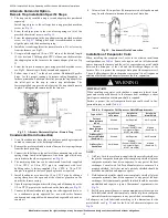
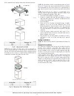
Страница 17: ...Table 11 footnotes for other return air restrictions A200426 Fig 28 Upflow Return Air Configurations and Restrictions A200425 Fig 29 Horizontal Return Air Configurations and Restrictions NOTE Refer to...

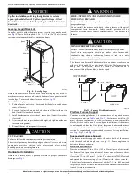
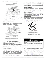
Страница 18: ...ks or bricks Condensate Trap section for required and recommended clearances for trap installation see Fig 6 Fig 21 and Fig 32 Suspended Furnace Support The furnace must be supported under the entire...

Страница 19: ...of the bottom and downward facing side may also be used The upward facing side of the casing cannot be used as a return air connection see Fig 29 Bottom Return Air Inlet These furnaces are shipped wit...

Страница 20: ...s sealed to the furnace casing and terminating outside the space containing the furnace Secure ductwork with proper fasteners for type of ductwork used Seal supply and return duct connections to furna...

Страница 21: ...661 0 07 17 0 12 31 0 13 33 0 20 51 0 31 79 1600 755 0 08 19 0 15 38 0 16 40 0 24 61 1800 850 0 08 21 0 18 47 0 18 47 0 29 73 2000 944 0 09 23 0 22 56 0 21 54 2200 1038 0 09 24 0 26 66 0 25 62 Face V...

Страница 22: ...810 1805 1785 CF Switches SW3 3 SW3 2 SW3 1 Low Clg Default OFF OFF ON 695 700 Note 4 Cooling SW2 Low Cooling SW3 OFF ON OFF 870 885 880 880 Note 4 OFF ON ON 1045 1060 1070 1070 1070 1070 Note 4 ON OF...

Страница 23: ...ore and during supply pipe pressure test After all connections have been made purge lines and check for leakage at furnace prior to operating furnace The gas supply pressure shall be within the maximu...

Страница 24: ...7 8 inch for 115 VAC Electric GAS SUPPLY MANUAL SHUT OFF VALVE REQUIRED SEDIMENT TRAP UNION NOTE Union may be inside the vestibule where permitted by local codes FRONT WARNING ELECTRICAL SHOCK FIRE OR...

Страница 25: ...0263 A190264 Fig 38 Installing J Box When Used External Electrical Box on Furnace Casing NOTE Check to ensure that external electrical box does not interfere with duct work gas piping or the indoor co...

Страница 26: ...in relief wire tie on furnace wiring harness 5 Connect field ground wire and factory ground wire to green ground screw on J Box mounting bracket see Fig 38 6 Connect power cord power and neutral leads...

Страница 27: ...trolled by a standard type thermostat Refer to the instructions supplied with the User Interface for complete details Alternate Power Supplies This furnace is designed to operate on utility generated...

Страница 28: ...MAXIMUM FUSE OR CKT BKR AMPS Time delay type is recommended Maximum Minimum 48060C17 115 60 1 127 104 11 4 12 6 14 29 15 60080C21 115 60 1 127 104 14 3 15 4 12 37 20 66100C21 115 60 1 127 104 14 3 15...

Страница 29: ...Speed Variable Furnace with Single Speed Air Conditioner A190369 Fig 44 1 Speed Variable Furnace with Two Speed Air Conditioner A190368 Fig 45 1 Speed Variable Furnace with Single Speed Heat Pump Dual...

Страница 30: ...enting systems This furnace is also CSA approved for venting with M G DuraVentR PolyProR or Centrotherm InnoFlueR polypropylene venting systems using single wall straight and flex and required fitting...

Страница 31: ...ewall For references to clearances required by National code authorities see Fig 60 OPTIONAL CONFIGURATION FOR COMBUSTION Ventilated Combustion Air Systems In a ventilated combustion air option the ve...

Страница 32: ...6 Termination or termination kit should be positioned where vent vapors are not objectionable Direct Vent 2 Pipe System Direct vent 2 pipe vent and combustion air pipes must terminate outside the stru...

Страница 33: ...umber of fittings multiplied by the deduction for each type of fitting used see Table 19 A200089 NOTE Only connect combustion air inlet moisture drain downstream of the furnace trap assembly as shown...

Страница 34: ...used for Alberta and Saskatchewan terminations NOTE Polypropylene venting systems MAY require additional deductions from the MEVL or additions to the TEVL for vent terminations and flexible pipe secti...

Страница 35: ...nnection see Fig 12 Use a flat blade screwdriver and tap on the knockout on opposite sides where the knockout meets the casing Fold the knockout down with duct pliers and work the knockout back and fo...

Страница 36: ...PYLENE VENT SYSTEMS SEE POLYPROPYLENE VENT SYSTEM MANUFACTURER S INSTRUCTIONS 13 After pipes have been cut and pre assembled apply generous layer of cement primer to pipe fitting socket and end of pip...

Страница 37: ...in 102 mm flashing for a 2 in 50 mm ND concentric vent or a 5 in diameter 127 mm flashing for a 3 in 80 mm ND concentric vent kit For two pipe or single pipe vent systems a flashing for each pipe of t...

Страница 38: ...cation for termination kit using the guidelines provided in section Locating The Vent Termination in this instruction 1 Cut two holes one for each pipe of appropriate size for pipe size being used 2 L...

Страница 39: ...y See Notes for Venting Options Notes for Venting Options 1 Attach vent pipe adapter with gasket to furnace casing 2 Align notches in rubber coupling over standoffs on adapter Slide clamps over the co...

Страница 40: ...636 ULC S636 Royal Pipe Schedule 40 ULC S636 ULC S636 ULC S636 ULC S636 PVC and ABS pipe may use either DWV or pressure rated fittings Colored or tinted solvents or primers must be used where required...

Страница 41: ...in some cases 13 Elbow and pipe sections within the furnace casing and at the vent termination should not be included in vent length or elbow count 14 The minimum pipe length is 5 ft 2 M linear feet m...

Страница 42: ...ere 70 ft 22 M Use length of the longer of the vent or air inlet piping system Add equiv length of 3 90 long radius elbows use the highest number of elbows for either the vent or inlet pipe 3 x 3 ft 0...

Страница 43: ...located on public property 7 ft 2 1 M Clearance under a veranda porch deck or balcony N P No operable windows doors or intakes of any type are permitted on Wall B between the vent termination and the...

Страница 44: ...12 in 305 mm for appliances 50 000 BTUh 15kW K Clearance to a mechanical air supply inlet 6 ft 1 8 M 3ft 9 M above if within 10 ft 3 M horizontally L Clearance under a veranda porch deck or balcony 12...

Страница 45: ...he side of the opening 1 ft 3M above the opening Manufacturer s Recommendation See Note 8 K Clearance to a mechanical air supply inlet 6 ft 1 8 M 3ft 9 M above if within 10 ft 3 M horizontally L Clear...

Страница 46: ...172mm for 2 in 51mm Abandoned masonry used as raceway per code 12 in 305 mm min from overhang or roof Maintain 12 in 305mm minimum clearance above highest anticipated snow level or grade whichever is...

Страница 47: ...and Continuous Fan airflows The Setup Switch locations are shown and described on Fig 65 The setup switches are also shown on the unit wiring label Setup Switches SW1 The furnace control has 8 setup...

Страница 48: ...are used for applications using a communicating User Interface and to adjust airflow SW4 3 is used to adjust airflow Refer to the Adjustments section for setup switch configurations Refer to User Inte...

Страница 49: ...een 4 5 in w c 1125 Pa and 13 6 in w c 3388 Pa i Remove jumper across thermostat connections to terminate call for heat Wait until the blower off delay is completed j Turn furnace gas valve electric s...

Страница 50: ...3 0 1525 800 2 4 2 5 2 6 2 7 2 7 2 8 825 2 3 2 3 2 4 2 5 2 6 2 7 to 850 2 1 2 2 2 3 2 4 2 4 2 5 875 2 0 2 1 2 2 2 2 2 3 2 4 900 1 9 2 0 2 0 2 1 2 2 2 2 5400 925 1 8 1 9 1 9 2 0 2 1 2 1 1646 950 1 8 1...

Страница 51: ...00 950 2 1 2 2 2 2 2 3 2 4 2 4 914 975 2 0 2 0 2 1 2 2 2 3 2 3 1000 1 9 1 9 2 0 2 1 2 1 2 2 775 2 9 3 0 3 1 3 1 3 1 3 1 800 2 7 2 8 2 9 3 0 3 1 3 1 3001 825 2 6 2 6 2 7 2 8 2 9 3 0 915 850 2 4 2 5 2 6...

Страница 52: ...l truncate at 2200 CFM on applicable models The high speed or single speed cooling airflow is adjusted by turning Setup switches SW2 1 SW2 2 and SW2 3 either ON or OFF Select the required airflow from...

Страница 53: ...must be performed by trained service personnel A qualified service person should inspect the furnace once a year General These instructions are written as if the furnace is installed in an upflow app...

Страница 54: ...be present at control and all blower OFF delays must be completed a Leave 115 v power to furnace turned on b Look into blower access door sight glass for current LED status c Remove blower door NOTE...

Страница 55: ...lower wheel and motor annually The inducer and blower motors are pre lubricated and require no additional lubrication Clean blower motor and wheel as follows 1 Turn off electrical supply to furnace 2...

Страница 56: ...b on the housing 11 Reinstall blower assembly in furnace 12 Reinstall two screws securing blower assembly to blower deck NOTE Refer to motor speed lead relocation if leads were not identified before d...

Страница 57: ...0 Turn power on at external disconnect fuse or circuit breaker 11 Run the furnace through two complete heating cycles to check for proper operation 12 Install control door when complete Servicing Hot...

Страница 58: ...ing Condensate Drain and Trap NOTE If the condensate trap is removed a new gasket between the trap and collector box is required Verify a condensate trap gasket is included in the service kit or obtai...

Страница 59: ...furnace control door WARNING ELECTRICAL SHOCK FIRE OR EXPLOSION HAZARD Failure to follow this warning could result in personal injury or death or property damage Before installing modifying or servic...

Страница 60: ...ive seconds after the GVR closes a 2 second flame proving period begins The HSI igniter will remain energized until the flame is sensed or until the 2 second flame proving period begins d Flame Provin...

Страница 61: ...the DHUM input logic is reversed The DHUM input is turned ON when no dehumidify demand exists Once 24 vac is detected by the furnace control on the DHUM input the furnace control dehumidification capa...

Страница 62: ...pump See Fig 42 and thermostat wiring for connections When installed with a heat pump the furnace control automatically changes the timing sequence to avoid long blower off times during demand defros...

Страница 63: ...setup switch SW1 1 in the ON position The AMBER LED are erased after 72 hours or can be manually erased by putting setup switch SW1 1 in the ON position and jumpering R W W1 and Y Y2 simultaneously s...

Страница 64: ...during the trial for ignition period the control will repeat the ignition sequence 3 more times before lockout 14 occurs Iffl ame signal is lost during the blower on delay period blower will come on...

Страница 65: ...ither the BLACK or WHITE power leads between the furnace control and the blower motor If you have a power choke disconnect it and check continuity YES YES NO NO Is there 12 VDC at PL13 7 RED and PL13...

Страница 66: ...t up Operating and Service and Maintenance Instructions Manufacturer reserves the right to change at any time specifications and designs without notice and without obligations 66 346011 2 revA A200312...

Страница 67: ...sh Poor inducer flow Excess wind 31 PRESSURE TRANSDUCER INPUT DOES NOT SENSE TARGET PRESSURE OR PRESSURE IS OUT OF RANGE Check for Excessive wind Proper vent sizing Restricted vent Defective inducer m...

Страница 68: ...company of your choice BRYANT HEATING COOLING SYSTEMS a division of Carrier Corporation 7310 West Morris Street Indianapolis IN 46231 U S A Have available the model number series number and serial num...

Отзывы: