912SE: Product Data
Manufacturer reserves the right to change, at any time, specifications and designs without notice and without obligations.
3
MODEL NUMBER NOMENCLATURE
A220582
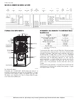
FURNACE COMPONENTS
A190145
For California Residents:
If installed with a manufactured (mobile) home conversion kit in
SCAQMD: This furnace does not meet the SCAQMD Rule 1111 14 ng/J
NOx emission limit, and thus is subject to a mitigation fee of up to $450.
This furnace is not eligible for the Clean Air Furnace Rebate Program:
www.CleanAirFurnaceRebate.com
MINIMUM CLEARANCES TO COMBUSTIBLE
MATERIALS
The furnace should be sized to provide 100 percent of the design heating
load requirement plus any margin that occurs because of furnace model
size capacity increments. None of the furnace model sizes can be used if
the heating load is 20,000 BTU or lower. Use Air Conditioning
Contractors of America (Manual J and S); American Society of Heating,
Refrigerating, and Air-Conditioning Engineers; or other approved
engineering method to calculate heating load estimates and select the
furnace. Excessive oversizing of the furnace may cause the furnace
and/or vent to fail prematurely, customer discomfort and/or vent
freezing.
Failure to follow these guidelines is considered faulty installation and/or
misapplication of the furnace; and resulting failure, damage, or repairs
may impact warranty coverage.
1
Heat
Exchanger
9
2
Tier/NOx
8
3
AFUE/NOx
7
4
Heating Stages
M
5
Major
Series
B
6, 7
Cooling
Capacity (CFM)
42
8 - 10
Heat Input
060
11
Motor Type
C
12 - 13
Width
17
14
Voltage
(1-phase)
A
15
Un-used
-
16
Minor
Series
A
|
|
|
|
|
|
|
|
|
|
|
|
-
A
B
C
---
14 = 14.2"
17 = 17.5"
21 = 21.0"
24 = 24.5"
C = Constant Airflow
Variable- Speed
(VCA) ECM
V = Variable-Speed
(VCT) PWM
M = Multi 18-Speed
Constant Torque
(MCT) ECM
026 = 26,000 BTU/h
040 = 40,000 BTU/h
060 = 60,000 BTU/h
---
A = 110V/60Hz
B = 230V/50Hz
A
B
C
D
---
8 = 80%
9 = 90+%
0 = Base
1 = Legacy Line
2 = Preferred
3 = Ultra Low Nox
8 = Evolution
0 = 80%
1 = 80% Low NOx
(Not Ultra Low
NOx)
2 = 92%
5 = 95%
6 = 96%
7 = 97%
8 = 98%
24 = 800 CFM
30 = 1000 CFM
36 = 1200 CFM
42 = 1400 CFM
48 = 1600 CFM
60 = 2000 CFM
66 = 2200 CFM
M = Modulating
T = Two Stage
S = Single Stage
C = Single Stage
Communicating
RATING PLATE NOT SHOWN
(LOCATED ON BLOWER DOOR)
GAS VALVE
MAIN LIMIT SWITCH
(BEHIND GAS VALVE)
ELECTRICAL JUNCTION
BOX (IF REQUIRED,
LOCATION MAY VARY)
OPERATING INSTRUCTIONS
NOT SHOWN (LOCATED ON
MAIN FURNACE DOOR, SEE
OPERATING INSTRUCTIONS
INSIDE DOOR FIGURE).
FURNACE
CONTROL
BOARD
MANUAL RESET
ROLLOUT SWITCH
FLAME
SENSOR
MANUAL RESET
ROLLOUT SWITCH
GAS BURNER
HOT SURFACE
IGNITER
INDUCER MOTOR
ASSEMBLY
BLOWER AND
MOTOR
BLOWER DOOR
SAFETY SWITCH
POSITION
CLEARANCE
Rear
0 (0 mm)
Front (Combustion air openings in
furnace and in structure)
1 in. (25 mm)
Required for service
*
*. Consult your local building codes
24 in. (610 mm)
†
†. Recommended
All Sides of Supply Plenum
1 in. (25 mm)
Sides
0 (0 mm)
Vent
0 (0 mm)
Top of Furnace
1 in. (25 mm)


