25
de-energize via unit disconnect switch operation of the conve-
nience outlet is desired, connect the source leads to the load side
of the unit disconnect. On a unit without a unit-mounted discon-
nect, connect the source leads to compressor contactor C and
indoor fan contactor IFC pressure lugs with unit field power leads
Fig. 37 — Power Wiring Connections (Sizes 08-14)
Fig. 38 — Power Wiring Connections (Sizes 16)
Field power wires are connected to the unit at line-side pres-
sure lugs on compressor contactor C and indoor fan contactor IFC
(see wiring diagram label for control box component arrange-
ment) or at factory-installed option non-fused disconnect switch.
Max wire size is #4 AWG (copper only).
NOTE: TEST LEADS – Unit may be equipped with short
leads (pigtails) on the field line connection points on contactor
C or optional disconnect switch. These leads are for factory
run-test purposes only; remove and discard before connecting
field power wires to unit connection points. Make field power
connections directly to line connection pressure lugs only.
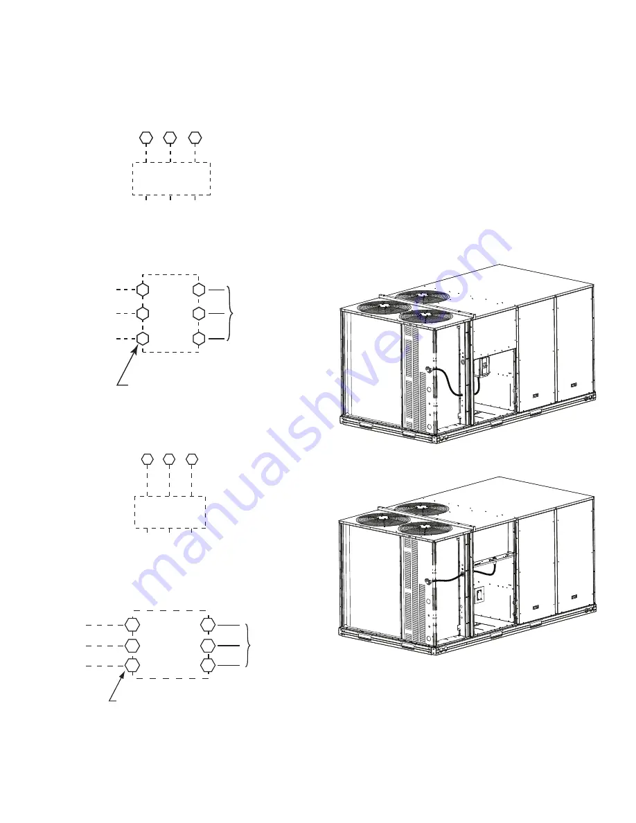
FIELD POWER SUPPLY (SIZE 16) —
For those units
without through-the-curb power, conduit must be used to route the
main power from the condenser end, via the power entry in the
corner post of the unit (see Fig. 39 and 40) to either the factory op-
tion disconnect or the bottom of the control box. 1 in. conduit is
provided wrapped around compressor. A second conduit is pro-
vided with factory installed powered convenience outlet. For those
units that require conduit larger than 1 in., it must be field sup-
plied. Fig. 39 and 40 show the wire routings.
Fig. 39 — Conduit into Factory Option Disconnect
Fig. 40 — Conduit into Control Box
If the field disconnect is larger than 100A, it must be attached
to the unit using accessory CRDISBKT001A00 — disconnect
switch bracket (see Fig. 41). Follow the instructions provided with
this accessory. For smaller field disconnects, be sure to use
1
/
2
in.
screws to mount the disconnect directly to the end panel (see
Fig. 42). In either case, set the disconnect vertical location on the
unit so that a 90 degree fitting can be used to connect the conduit
to the disconnect.
C
IFC
Di
s
connect f
a
ctory te
s
t le
a
d
s
a
nd di
s
c
a
rd.
Option
a
l
Di
s
connect
S
witch
1
3
1
3
L1
L2
L
3
20
8
/2
3
0-
3
-60
460-
3
-60
575-
3
-60
Unit
s
Witho
u
t Di
s
connect Option
Unit
s
With Di
s
connect Option
1
3
5
2
4
6
L1
L2
L
3
F
a
ctory
Wiring
Di
s
connect
per
NEC
11
Unit
s
Witho
u
t Di
s
connect Option
Unit
s
With Di
s
connect Option
2
4
6
1
3
5
L1
L2
L
3
Option
a
l
Di
s
connect
S
witch
Di
s
connect f
a
ctory te
s
t le
a
d
s
; di
s
c
a
rd.
F
a
ctory
Wiring
11
12
1
3
L1
L2
L
3
TB1
20
8
/2
3
0-
3
-60
460-
3
-60
575-
3
-60
Di
s
connect
per
NEC
Содержание 580J*16D Series
Страница 4: ...4 Fig 2 Unit Dimensional Drawing Sizes 08 09 and 12 ...
Страница 5: ...5 Fig 2 Unit Dimensional Drawing Sizes 08 09 and 12 cont ...
Страница 6: ...6 Fig 3 Unit Dimensional Drawing Size 14 ...
Страница 7: ...7 Fig 3 Unit Dimensional Drawing Size 14 cont ...
Страница 8: ...8 Fig 4 Unit Dimensional Drawing Size 16 ...
Страница 9: ...9 Fig 4 Unit Dimensional Drawing Size 16 cont ...
Страница 15: ...15 Fig 9 580J 16 Roof Curb Details ...
Страница 32: ...32 Fig 58 580J 08 14 Typical Perfect Humidity Dehumidification System Humidistat Wiring ...
Страница 33: ...33 Fig 59 580J 16 Typical Perfect Humidity Dehumidification System Humidistat Wiring ...
Страница 48: ...48 Fig 67 580J 08 12N P Typical RTU Open System Control Wiring Diagram ...
Страница 49: ...49 Fig 68 580J 08 14 Typical RTU Open System Control Wiring Diagram ...
Страница 50: ...50 Fig 69 580J 16 Typical RTU Open System Control Wiring Diagram ...
Страница 51: ...51 Fig 70 580J 8 14 Typical RTU Open System Control Wiring Diagram with Perfect Humidity System ...
Страница 52: ...52 Fig 71 580J 16 Typical RTU Open System Control Wiring Diagram with Perfect Humidity System ...


