background image

36

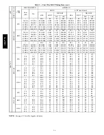
Table 5 — Unit Wire/MOCP Sizing Data (cont)

UN

IT

N

O

M

.V

---

P

H

---

H

Z

IFM

TYPE

ELECTRIC HEATER

w/PWRD C.O.

Nom

(kW)

FLA

NO P.E.

w/ P.E. (pwrd fr/unit)

MCA

MOCP

DISC. SIZE

MCA

MOCP

DISC. SIZE

FLA

LRA

FLA

LRA

558J

*12D

208/

230

---

3

---

60

STD

---

---

48.5

60

51

263

52.3

60

56

267

7.8/10.4

21.7/25.0

48.5/48.5

60/60

51/51

263/263

52.3/52.3

60/60

56/56

267/267

12.0/16.0

33.4/38.5

54.3/60.6

60/70

51/56

263/263

59.0/65.4

60/70

56/60

267/267

24.0/32.0

66.7/77.0

95.9/108.8

100/110

88/100

263/263

100.6/113.5

110/125

93/104

267/267

31.8/42.4

88.4/102.0

123.0/140.0

125/150

113/129

263/263

127.8/144.8

150/150

118/133

267/267

37.6/50.0 104.2/120.3 142.8/132.8

150/150

131/150

263/263

147.5/137.6

150/150

136/154

267/267

MED

---

---

53.3

60

57

306

57.1

70

61

310

7.8/10.4

21.7/25.0

53.3/53.3

60/60

57/57

306/306

57.1/57.1

70/70

61/61

310/310

12.0/16.0

33.4/38.5

60.3/66.6

70/70

57/61

306/306

65.0/71.4

70/80

61/66

310/310

24.0/32.0

66.7/77.0

101.9/114.8

110/125

94/106

306/306

106.6/119.5

110/125

98/110

310/310

31.8/42.4

88.4/102.0

129.0/146.0

150/150

119/134

306/306

133.8/150.8

150/175

123/139

310/310

37.6/50.0 104.2/120.3 148.8/138.8

150/150

137/155

306/306

153.5/143.6

175/175

141/160

310/310

HIGH

---

---

58.3

70

62

315

62.1

70

67

319

7.8/10.4

21.7/25.0

58.3/58.3

70/70

62/62

315/315

62.1/62.1

70/70

67/67

319/319

12.0/16.0

33.4/38.5

66.5/72.9

70/80

62/67

315/315

71.3/77.6

80/80

67/71

319/319

24.0/32.0

66.7/77.0

108.1/121.0

110/125

99/111

315/315

112.9/125.8

125/150

104/116

319/319

31.8/42.4

88.4/102.0

135.3/152.3

150/175

124/140

315/315

140.0/157.0

150/175

129/144

319/319

37.6/50.0 104.2/120.3 155.0/145.1

175/175

143/161

315/315

159.8/149.8

175/175

147/165

319/319

46

0

---

3

---

60

STD

---

---

23.7

30

25

125

25.5

30

27

127

13.9

16.7

26.9

30

25

125

29.1

30

27

127

16.5

19.8

30.8

35

28

125

33.0

35

30

127

33.0

39.7

55.6

60

51

125

57.9

60

53

127

41.7

50.2

68.8

70

63

125

71.0

80

65

127

50.0

60.1

66.1

70

75

125

68.4

70

77

127

MED

---

---

25.5

30

27

147

27.3

30

29

149

13.9

16.7

29.1

30

27

147

31.4

35

29

149

16.5

19.8

33.0

35

30

147

35.3

40

32

149

33.0

39.7

57.9

60

53

147

60.1

70

55

149

41.7

50.2

71.0

80

65

147

73.3

80

67

149

50.0

60.1

68.4

80

77

147

70.6

80

79

149

HIGH

---

---

28.5

35

31

151

30.3

35

33

153

13.9

16.7

32.9

35

31

151

35.1

40

33

153

16.5

19.8

36.8

40

34

151

39.0

40

36

153

33.0

39.7

61.6

70

57

151

63.9

70

59

153

41.7

50.2

74.8

80

69

151

77.0

80

71

153

50.0

60.1

72.1

80

80

151

74.4

80

82

153

57

5

---

3

---

60

STD

---

---

17.9

20

19

95

21.7

25

23

99

17.0

20.4

30.1

35

28

95

34.9

35

32

99

34.0

40.9

55.8

60

51

95

60.5

70

56

99

51.0

61.3

66.9

70

75

95

70.7

80

79

99

MED

---

---

18.7

25

20

106

25.3

30

24

110

17.0

20.4

31.1

35

29

106

39.4

40

33

110

34.0

40.9

56.8

60

52

106

65.0

70

57

110

51.0

61.3

66.9

70

76

106

75.2

80

80

110

HIGH

---

---

21.5

25

23

120

23.6

30

27

124

17.0

20.4

34.6

35

32

120

37.3

40

36

124

34.0

40.9

60.3

70

55

120

62.9

70

60

124

51.0

61.3

70.4

80

79

120

73.1

80

83

124

NOTE

: See page 39 for table legend and notes.

558J

***D

Содержание 558J***D

Страница 1: ...assistance The qualified installer or agency must use factory authorized kits or accessories when modifying this product Refer to the individual instructions packaged with the kits or accessories when installing Follow all safety codes Wear safety glasses and work gloves Use quenching cloths for brazing operations and have a fire extinguisher available Read these instructions thoroughly and follow...

Страница 2: ...ms Do not use R 22 service equipment or components on Puron refrigerant equipment WARNING PERSONAL INJURY AND ENVIRONMENTAL HAZARD Failure to follow this warning could cause personal injury or death Relieve pressure and recover all refrigerant before system repair or final unit disposal Wear safety glasses and gloves when handling refrigerants Keep torches and other ignition sources away from refr...

Страница 3: ...3 Horizontal Connections Economizer Vertical Connections Economizer C08609 Fig 1 Unit Dimensional Drawing 08 09 and 12 Size Units 558J D ...

Страница 4: ...4 C08610 Fig 1 Unit Dimensional Drawing 08 09 and 12 Size Unit cont 558J D ...

Страница 5: ...5 Horizontal Connections Economizer Vertical Connections Economizer C08611 Fig 2 Unit Dimensional Drawing 14 Size Unit 558J D ...

Страница 6: ...gs See Fig 3 NOTE Consider also the effect of adjacent units Do not install unit in an indoor location Do not locate air inlets near exhaust vents or other sources of contaminated air Although unit is weatherproof avoid locations that permit water from higher level runoff and overhangs to fall onto the unit 18 457 42 1067 18 457 42 1067 1 Required bottom condensate drain connection Otherwise 36 91...

Страница 7: ...an Step 3 Inspect unit Inspect unit for transportation damage File any claim with transportation agency Confirm before installation of unit that voltage amperage and circuit protection requirements listed on unit data plate agree with power supply provided Step 4 Provide Unit Support Roof Curb Mount Accessory roof curb details and dimensions are shown in Fig 4 Assemble and install accessory roof c...

Страница 8: ...8 558J 08 558J 08 14D 14D ROOFCURB ACCESSORY CRRFCURB003A01 CRRFCURB004A01 1 2 356 2 0 610 UNIT SIZE UNIT SIZE C08504 Fig 4 Roof Curb Details 558J D ...

Страница 9: ...a minimum clearance Minimum clearance is not required around ductwork Step 6 Rig and Place Unit Keep unit upright and do not drop Spreader bars are not required if top crating is left on unit Rollers may be used to move unit across a roof Level by using unit frame as a reference See Table 1 and Fig 6 for additional information Lifting holes are provided in base rails as shown in Fig 6 Refer to rig...

Страница 10: ...he insulation side down Seals around duct openings must be tight See Fig 7 C06108 Fig 7 Horizontal Conversion Panels Field supplied flanges should be attached to horizontal duct openings and all ductwork should be secured to the flanges Insulate and weatherproof all external ductwork joints and roof or building openings with counter flashing and mastic in accordance with applicable codes Do not co...

Страница 11: ...od remove the filter access panel See Fig 8 3 Locate the 2 screws holding the metal tray to the basepan and remove Locate and cut the 2 plastic tie wraps securing the assembly to the damper See Fig 10 Be careful to not damage any wiring or cut tie wraps securing any wiring 4 Carefully lift the hood assembly with metal tray through the filter access opening and assemble per the steps outlined in Ec...

Страница 12: ...e filter clips which are located underneath the hood top Insert the aluminum filter into the bottom filter rack hood divider Push the filter into position past the open filter clips Close the filter clips to lock the filter into place See Fig 13 DIVIDER BAROMETRIC RELIEF CLEANABLE ALUMINUM FILTER FILTER HOOD FILTER CLIP OUTSIDE AIR C08634 Fig 13 Economizer Filter Installation 6 Caulk the ends of t...

Страница 13: ... with local codes to ensure this method is acceptable in your area If a de energize via unit disconnect switch operation of the convenience outlet is desired connect the source leads to the load side of the unit disconnect On a unit without a unit mounted disconnect connect the source leads to compressor contactor C and indoor fan contactor IFC pressure lugs with unit field power leads All units e...

Страница 14: ...iring must comply with the NEC and local requirements Convenience Outlets ELECTRICAL OPERATION HAZARD Failure to follow this warning could result in personal injury or death Units with convenience outlet circuits may use multiple disconnects Check convenience outlet for power status before opening unit for service Locate its disconnect switch if appropriate and open it Tag out this switch if neces...

Страница 15: ... Duty Cycle the unit powered convenience outlet has a duty cycle limitation The transformer is intended to provide power on an intermittent basis for service tools lamps etc it is not intended to provide 15 amps loading for continuous duty loads such as electric heaters for overnight use Observe a 50 limit on circuit loading above 8 amps i e limit loads exceeding 8 amps to 30 minutes of operation ...

Страница 16: ...ant approved accessory thermostat according to installation instructions included with the accessory For complete economizer function select a two stage cooling thermostat Locate the thermostat accessory on a solid wall in the conditioned space to sense average temperature in accordance with the thermostat installation instructions If the thermostat contains a logic circuit requiring 24 v power us...

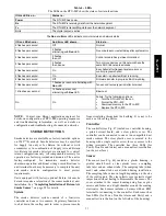
Страница 17: ...below the indoor supply fan outlet Access is through the indoor access panel Heater modules slide into the compartment on tracks along the bottom of the heater opening See Fig 24 Fig 25 and Fig 26 Unit heaters are marked with Heater Model Numbers But heaters are ordered as and shipped in cartons marked with a corresponding heater Sales Package part number See Table 2 for correlation between heater...

Страница 18: ...a special Single Point Box without any fuses The accessory Single Point Boxes contain a set of power taps and pigtails to complete the wiring between the Single Point Box and the unit s main control box terminals Refer to accessory heater and Single Point Box installation instructions for details on tap connections ALLIED PA MODEL NO ERIAL NO CORP 11 13 21 23 OD 22 2 3 1 23 ISTED AIR NDITIONING UI...

Страница 19: ... DIP switches The RTU MP control is factory mounted in the 558J D unit s main control box to the left of the CTB See Fig 30 Factory wiring is completed through harnesses connected to the CTB Field connections for RTU MP sensors will be made at the Phoenix connectors on the RTU MP board The factory installed RTU MP control includes the supply air temperature SAT sensor The outdoor air temperature O...

Страница 20: ...20 C09608 Fig 31 RTU MP System Control Wiring Diagram 558J D ...

Страница 21: ... Stage 2 Relay State heat_2 DO Relay 24VAC 1A J1 5 Power Exhaust Relay State aux_2 DO Relay 24VAC 1A J11 3 Dehumidification Relay State humizer DO Relay 24VAC 1A J11 7 8 LEGEND AI Analog Input AO Analog Output DI Discrete Input DO Discrete Output These inputs if installed take the place of the default input on the specific channel according to schematic Parallel pins J5 1 J2 6 J5 3 J1 10 J5 5 J1 2...

Страница 22: ...ied Bryant space temperature sensor is required with the RTU MP to monitor space temperature There are 3 sensors available for this application S 33ZCT55SPT space temperature sensor with override button S 33ZCT56SPT space temperature sensor with override button and setpoint adjustment S 33ZCT59SPT space temperature sensor with LCD liquid crystal display screen override button and setpoint adjustme...

Страница 23: ...o GND The outdoor enthalpy changeover setpoint is set at the enthalpy controller Differential Enthalpy Control Differential enthalpy control is provided by sensing and comparing the outside air and return air enthalpy conditions Install the outdoor air enthalpy control as described above Add and install a return air enthalpy sensor ESL LOW GND 24V GRA BLK RED ECONO MOTOR 4 20 Main VDC Out 4 20 Mai...

Страница 24: ...P J4 3 See Fig 41 SEN COM J4 2 J4 3 IAQ Sensor 24 VAC C08462 Fig 41 RTU MP Indoor CO2 Sensor 33ZCSENCO2 Connections Outdoor Air Quality Sensor PNO 33ZCSENCO2 plus weatherproof enclosure The outdoor air CO2 sensor is designed to monitor carbon dioxide CO2 levels in the outside ventilation air and interface with the ventilation damper in an HVAC system The OAQ sensor is packaged with an outdoor cove...

Страница 25: ...ccupancy and normally open N O or normally closed N C Also set MENU Schedules occupancy source to DI on off Input 8 or 9 is recommended for easy of installation Refer to Fig 29 and Table 3 for wire terminations at J5 Power Exhaust output Connect the accessory Power Exhaust contactor coil s per Fig 44 Power Exhaust J11 3 C TAN GRA PEC CTB THERMOSTAT C08464 Fig 44 RTU MP Power Exhaust Connections Sp...

Страница 26: ...Cview6 to the RTU MP s J12 local access port There are 2 password protected levels in the display User and Admin The user password is defaulted to 0000 but can be changed The Admin password is 1111 and cannot be changed There is a 10 minute auto logout if a screen is idle Contact your Bryant applications engineer for details on navigation and screen content Virtual BACview Virtual BACview is a fre...

Страница 27: ...ranged for vertical return configurations only All components necessary for operation are factory provided and mounted The unit is factory configured for immediate smoke detector shutdown operation additional wiring or modifications to unit terminal board may be necessary to complete the unit and smoke detector configuration to meet project requirements Units equipped with factory optional Return ...

Страница 28: ...nmental changes from triggering false alarms A rapid change in environmental conditions such as smoke from a fire causes the sensor to signal an alarm state but dust and debris accumulated over time does not For installations using two sensors the duct smoke detector does not differentiate which sensor signals an alarm or trouble condition Smoke Detector Locations Supply Air The Supply Air smoke d...

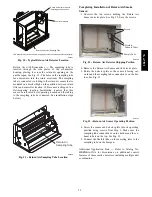
Страница 29: ...ted See installation steps below Return Air Sampling Tube C08129 Fig 51 Return Air Sampling Tube Location Completing Installation of Return Air Smoke Sensor 1 Unscrew the two screws holding the Return Air Sensor detector plate See Fig 52 Save the screws Flexible Exhaust Tubes Screws Sample Tube C08126 Fig 52 Return Air Detector Shipping Position 2 Remove the Return Air Sensor and its detector plat...

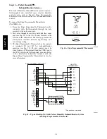
Страница 30: ...rol box The raceway provides the UL required clearance between high voltage and low voltage wiring 3 The Edge Programmable Thermostat has dry contacts at terminals D1 and D2 for dehumidification operation see Fig 55 The dry contacts must be wired between CTB terminal R and the PINK lead to the LTLO switch with field supplied wire nuts Refer to the installation instructions included with the Bryant...

Страница 31: ...2 0 16 0 33 4 38 5 60 5 66 9 70 70 56 62 256 256 65 3 71 6 70 80 60 66 260 260 18 6 24 8 51 7 59 7 83 4 93 4 90 100 77 86 256 256 88 1 98 1 90 100 81 90 260 260 24 0 32 0 66 7 77 0 102 1 115 0 110 125 94 106 256 256 106 9 119 8 110 125 98 110 260 260 31 8 42 4 88 4 102 0 129 3 146 3 150 150 119 135 256 256 134 0 151 0 150 175 123 139 260 260 460 3 60 STD 17 9 20 19 95 19 7 25 21 97 13 9 16 7 24 1 ...

Страница 32: ...12 0 16 0 33 4 38 5 66 5 72 9 70 80 61 67 261 261 71 3 77 6 80 80 66 71 265 265 18 6 24 8 51 7 59 7 89 4 99 4 90 100 82 91 261 261 94 1 104 1 100 110 87 96 265 265 24 0 32 0 66 7 77 0 108 1 121 0 110 125 99 111 261 261 112 9 125 8 125 150 104 116 265 265 31 8 42 4 88 4 102 0 135 3 152 3 150 175 124 140 261 261 140 0 157 0 150 175 129 144 265 265 460 3 60 STD 20 1 25 21 97 21 9 25 23 99 13 9 16 7 2...

Страница 33: ...16 0 33 4 38 5 54 3 60 6 50 60 50 56 262 262 59 0 65 4 60 70 54 60 266 266 18 6 24 8 51 7 59 7 77 1 87 1 80 90 71 80 262 262 81 9 91 9 90 100 75 85 266 266 24 0 32 0 66 7 77 0 95 9 108 8 100 110 88 100 262 262 100 6 113 5 100 125 93 104 266 266 31 8 42 4 88 4 102 0 123 0 140 0 125 150 113 129 262 262 127 8 144 8 150 150 118 133 266 266 460 3 60 STD 18 4 25 19 109 20 2 25 21 111 13 9 16 7 24 1 25 2...

Страница 34: ...16 0 33 4 38 5 60 3 66 6 70 70 55 61 267 267 65 0 71 4 70 80 60 66 271 271 18 6 24 8 51 7 59 7 93 1 93 1 90 100 76 86 267 267 87 9 97 9 90 100 81 90 271 271 24 0 32 0 66 7 77 0 101 9 114 8 110 125 94 106 267 267 106 6 119 5 110 125 98 110 271 271 31 8 42 4 88 4 102 0 129 0 146 0 150 150 119 134 267 267 133 8 150 8 150 175 123 139 271 271 460 3 60 STD 20 6 25 22 111 22 4 25 24 113 13 9 16 7 26 9 30...

Страница 35: ... 6 70 80 61 66 314 314 24 0 32 0 66 7 77 0 102 1 115 0 110 125 94 106 310 310 106 9 119 8 110 125 98 110 314 314 31 8 42 4 88 4 102 0 129 3 146 3 150 150 119 135 310 310 134 0 151 0 150 175 123 139 314 314 37 6 50 0 104 2 120 3 149 0 139 1 150 175 137 156 310 310 153 8 143 8 175 175 141 160 314 314 460 3 60 STD 21 5 25 23 123 23 3 30 25 125 13 9 16 7 24 1 25 23 123 26 4 30 25 125 16 5 19 8 28 0 30...

Страница 36: ...80 80 67 71 319 319 24 0 32 0 66 7 77 0 108 1 121 0 110 125 99 111 315 315 112 9 125 8 125 150 104 116 319 319 31 8 42 4 88 4 102 0 135 3 152 3 150 175 124 140 315 315 140 0 157 0 150 175 129 144 319 319 37 6 50 0 104 2 120 3 155 0 145 1 175 175 143 161 315 315 159 8 149 8 175 175 147 165 319 319 460 3 60 STD 23 7 30 25 125 25 5 30 27 127 13 9 16 7 26 9 30 25 125 29 1 30 27 127 16 5 19 8 30 8 35 2...

Страница 37: ...80 80 76 76 390 390 24 0 32 0 66 7 77 0 102 1 115 0 110 125 94 106 386 386 106 9 119 8 110 125 98 110 390 390 31 8 42 4 88 4 102 0 129 3 146 3 150 150 119 135 386 386 134 0 151 0 150 175 123 139 390 390 37 6 50 0 104 2 120 3 149 0 139 1 150 175 137 156 386 386 153 8 143 8 175 175 141 160 390 390 460 3 60 STD 29 5 40 31 181 31 3 40 33 183 13 9 16 7 29 5 40 31 181 31 3 40 33 183 16 5 19 8 29 5 40 31...

Страница 38: ...1 121 0 110 125 99 111 391 391 112 9 125 8 125 150 104 116 395 395 31 8 42 4 88 4 102 0 135 3 152 3 150 175 124 140 391 391 140 0 157 0 150 175 129 144 395 395 37 6 50 0 104 2 120 3 155 0 145 1 175 175 143 161 391 391 159 8 149 8 175 175 147 165 395 395 460 3 60 STD 31 7 40 33 183 33 5 40 35 185 13 9 16 7 31 7 40 33 183 33 5 40 35 185 16 5 19 8 31 8 40 33 183 34 0 40 35 185 33 0 39 7 56 6 60 52 18...

Страница 39: ...r operate a motor where a phase imbalance in supply voltage is greater than 2 Use the following formula to de termine the percentage of voltage imbalance Voltage Imbalance 100 x max voltage deviation from average voltage average voltage Example Supply voltage is 230 3 60 AB 224 v BC 231 v AC 226 v Average Voltage 224 231 226 681 3 3 227 Determine maximum deviation from average voltage AB 227 224 3...

Страница 40: ...unit is set on curb Manual outside air damper Two Position motorized outside air damper EconoMi er IV with control and integrated barometric relief EconoMi er2 without control for external signal and integrated barometric relief Power Exhaust Differential dry bulb sensor EconoMi er IV Outdoor enthalpy sensor Differential enthalpy sensor Electric Heaters Single Point kits Low Ambient Controls Therm...

Отзывы: