


- 12 -
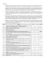
Table 2 – Cooling Tonnage vs. Airflow (CFM)
AIR CONDITIONING TONS
(12,000 BTU/HR)
AIRFLOW
(CFM)
040, 060, & 3T-
080 MODEL
5T-080 & 100
MODEL
120 MODEL
1-1/2
525 X
2
700 X X X
2-1/2
875 X X X
3
1050
X X X
3-1/2
1225
X X X
4
1400 X X
5
1750 X X
6
2100 X
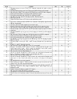
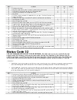
HIGH HEAT TEMPERATURE RISE TOO LOW - Generally, this indicates the HI solenoid in gas
valve GV has failed or the furnace is extremely underfired.
STEP ACTION YES
NO
GO
TO
1.
Remove the blower access panel. Disconnect User Interface ABCD connector (if used) or the
R thermostat lead (if used) from the furnace control board. If setup switch SW1-2 is ON then
set it to OFF.
2
2.
Depress the door switch. Use piece of tape to hold it closed.
3
3.
Jumper R and W/W1 thermostat terminals.
4
4.
When the furnace is running in low heat, clock the low heat gas rate. You have 16 minutes on
this first call for heat before unit switches to high heat. On propane installations check the
manifold pressure.
5
5.
When the furnace is running in high heat, clock the high heat gas rate. On propane
installations check the manifold pressure.
6
6.
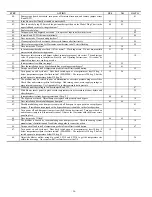
Is the high heat rate approximately the same as the low heat rate?
7
11
7.
Do you have 24 vac across gas valve terminals HI and C
OM
-24V on 2-stage gas valve during
high heat?
10 8
8.
You have an open wire or bad terminal on the BROWN wire from the high heat pressure
switch HPS to the gas valve GV. Repair it or replace the harness.
9
9.
Go to the page number indicated in Index for the CLEANUP AND STARTUP
INSTRUCTIONS.
INDEX
10.
Replace the gas valve.
9
11.
Is the high heat rate within 2% of that specified on the rating plate?
13
12
525
2
700
2
700
875
1050
875
700
875
2
1050
1050
1
1225
1225
1225
1400
1400
1225
1750
1
1750
1
1225
1750
2100
DEF.
DEF.
DEF.
040, 060, 3T-080
5T-080, 100
120
BASED ON 350 CFM/TON (SETUP SWITCH SW1-5 OFF)
SETUP SWITCH SW3 POSITIONS
MODEL
SIZE
600
2
800
2
800
1000 1200
1000
800
1000
2
1200
1200
1
1400
1400
1400
1600
1600
1400
2000
1
2000
1
1400
2000
2100
DEF.
DEF.
DEF.
040, 060, 3T-080
5T-080, 100
120
BASED ON 400 CFM/TON (SETUP SWITCH SW1-5 ON)
1. DEFAULT A/C AIRFLOW WHEN A/C SWITCHES ARE IN OFF POSITION
2. DEFAULT CONT. FAN AIRFLOW WHEN CF SWITCHES ARE IN OFF POSITION
3. SWITCH POSITIONS ARE ALSO SHOWN ON FURNACE WIRING DIAGRAM
SETUP SWITCH SW3 POSITIONS
MODEL
SIZE
AIR CONDITIONING (A/C) OR CONTINUOUS-FAN (CF)
AIRFLOW SELECTION CHART
Содержание 355AAV EVOLUTION
Страница 33: ...33 Fig 2 Schematic for 355MAV and 355AAV with ECM 2 5 Blower Motor...
Страница 34: ...34 Fig 3 Schematic for 355AAV with ECM 3 0 Blower Motor...
Страница 35: ...35 Fig 4 Schematic for 355BAV with ECM 2 5 Blower Motor...
Страница 42: ...42 A02281...
Страница 44: ...44 Replaces SM05 5 Form SM05 07 6 08...


