


III-22
(6)
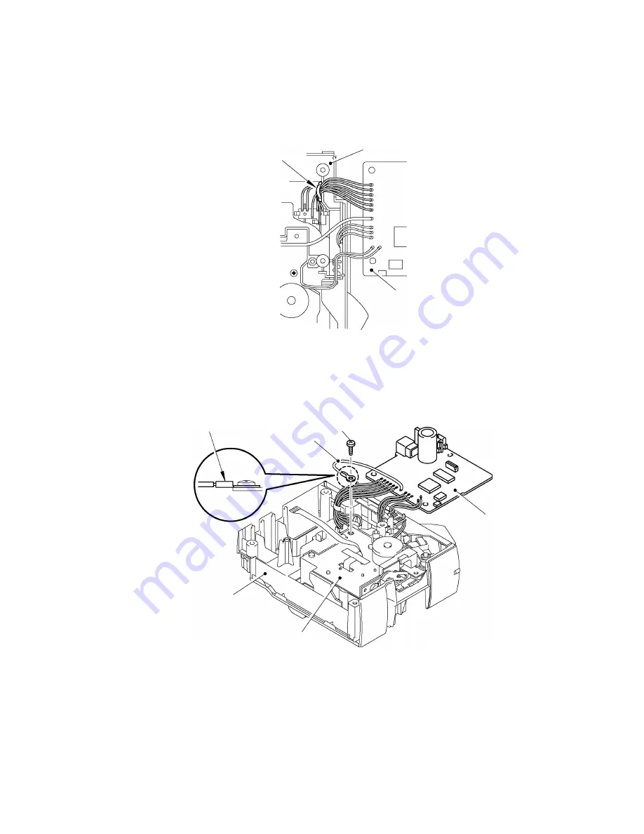
Bind the six harnesses of the switch ASSY at the center of the harness with the fixing tape.
Note 1: Use the transparent tape whose width is 12mm to bind the harness.
Note 2: When the harnesses have been already bound with the tape, check that they are
bound correctly. If not, bind the harnesses again with a new tape.
Fig. 3.1-33 Assembling the Main PCB ASSY (5)
(7)
Secure the FG harness onto the chassis ASSY with the one screw.
Fig. 3.1-34 Assembling the Main PCB ASSY (6)
Middle cover
Main PCB ASSY
Fixing tape
* The stepped side
should be at the top.
Screw
Chassis ASSY
Middle cover
FG harness
Main PCB ASSY
Содержание PT-2420PC
Страница 1: ...SERVICE MANUAL MODEL PT 2420PC ...
Страница 49: ...IV 6 2 Printing Failure ...
Страница 50: ...IV 7 3 The Indicator LED will not come on ...
Страница 51: ...IV 8 4 Interface Malfunctions ...
Страница 62: ......
Страница 63: ...Jan 2002 8V2029BE0 Printed in Japan ...


