IV
- 36
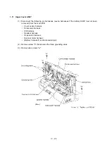
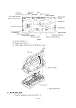
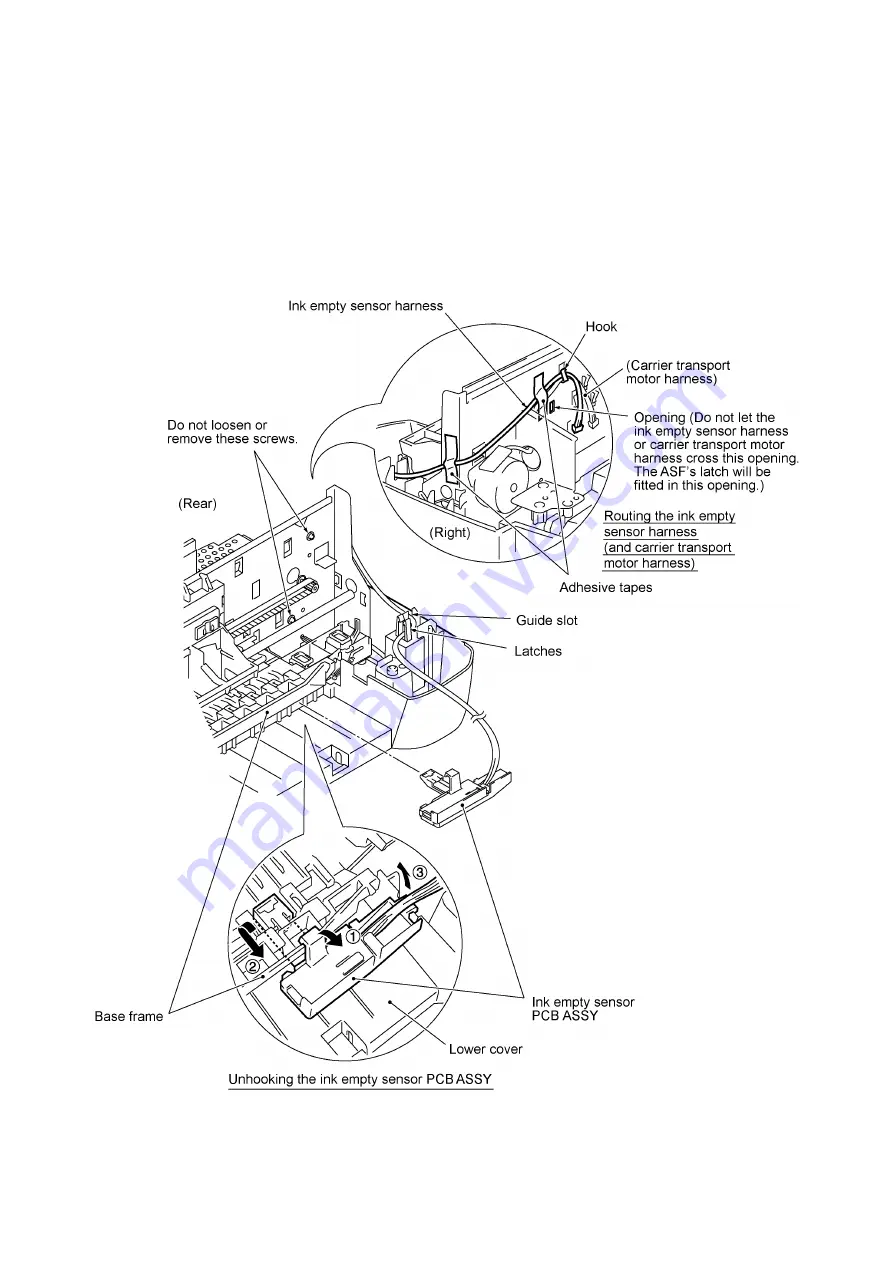
1.18 Ink Empty Sensor PCB ASSY
(1) Peel off adhesive tape that attaches the ink empty sensor harness to the frame chassis at
each of the rear and right side.
(2) Take out the ink empty sensor harness from the guide slot and the latches.
(3) Unhook the ink empty sensor PCB ASSY from the base frame in the direction of arrows
•
,
‚
,
and
ƒ
.
Содержание MFC-7050C
Страница 1: ...FACSIMILE EQUIPMENT SERVICE MANUAL MODEL MFC7050C ...
Страница 4: ...CHAPTER I GENERAL DESCRIPTION ...
Страница 10: ...CHAPTER II INSTALLATION ...
Страница 11: ...CONTENTS 1 INSTALLING THE UPDATE DATA TO THE FACSIMILE EQUIPMENT II 1 ...
Страница 14: ...CHAPTER III THEORY OF OPERATION ...
Страница 16: ...III 1 1 OVERVIEW ...
Страница 27: ...III 12 Location of Sensors and Actuators ...
Страница 30: ...III 15 ...
Страница 35: ...CHAPTER IV DISASSEMBLY REASSEMBLY AND LUBRICATION ...
Страница 41: ...IV 4 n n Disassembly Order Flow ...
Страница 51: ...IV 14 2 Remove the two screws from the scanner frame ASSY See the illustration on the next page ...
Страница 93: ...IV 56 1 33 Ink Foam 1 Take up the ink foam from the lower cover ...
Страница 94: ...IV 57 1 34 Harness Routing ...
Страница 96: ...IV 59 2 Control panel locks 3 Scanner frame ASSY and separation roller gear ...
Страница 97: ...IV 60 4 Top cover lock spring 5 Gear plate ASSY ...
Страница 98: ...IV 61 6 Hinges 7 Frame chassis ASSY ...
Страница 99: ...IV 62 8 Idle pulley holder 9 Maintenance ASSY ...
Страница 100: ...IV 63 10 Exit roller ASSY 11 Large feed roller ASSY ...
Страница 101: ...CHAPTER V MAINTENANCE MODE ...
Страница 108: ...V 6 Scanning Compensation Data List ...
Страница 123: ...CHAPTER VI ERROR INDICATION AND TROUBLESHOOTING ...
Страница 135: ...May 99 SM8XD115 Printed in Japan ...
Страница 136: ...MFC7050C Appendix 1 EEPROM Customizing Codes ...
Страница 153: ...E Power Supply PCB ...


