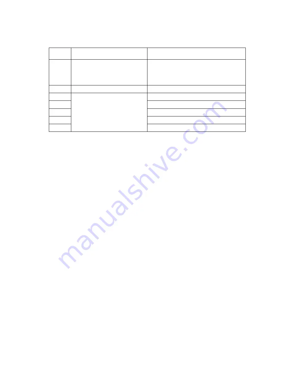
Brother FAX-8060P Скачать руководство пользователя страница 104

V

 - 24

WSW11 

(Busy tone setting)

Selector

No.

Function

Setting and Specifications

1

2

Frequency band range

No.

1

2

0

0

:

Narrows by 10 Hz

0

1

:

Initial value

1

x

:

Widens by 10 Hz

3

Not used.

4

1:  400-600/400-600 ms

5

ON/OFF time length ranges

1:  175-440/175-440 ms

6

(More than one setting allowed)

1:  700-800/700-800 ms

7

1:  110-410/320-550 ms

8

1:  100-660/100-660 ms

NOTE:

  WSW11 is not applicable in those countries where no busy tone detection is supported.

NOTE:

  The setting of WSW11 is effective only when selectors 5 and 6 of WSW05 are set to "0, 1" or

"1, 1" (Busy tone detection).

Selectors 1 and 2: Frequency band range

These selectors set the frequency band for busy tone to be detected.

Selectors 4 through 8:

ON/OFF time length ranges

These selectors set the ON and OFF time length ranges for busy tone to be detected.  If more than
one selector is set to "1," the ranges become wider.  For example, if selectors 4 and 5 are set to "1,"
the ON and OFF time length ranges are from 175 to 600 ms.

Содержание FAX-8060P

Страница 1: ...FACSIMILE EQUIPMENT SERVICE MANUAL MODEL FAX2600 FAX 8060P MFC4300 MFC4600 MFC 9060 ...

Страница 2: ...ht Brother 2000 All rights reserved No part of this publication may be reproduced in any form or by any means without permission in writing from the publisher Specifications are subject to change without notice ...

Страница 3: ...hat the facsimile equipment is always in best condition for the customer the service personnel must adequately understand and apply this manual This manual is made up of six chapters and appendices CHAPTER I GENERAL DESCRIPTION CHAPTER II INSTALLATION CHAPTER III THEORY OF OPERATION CHAPTER IV DISASSEMBLY REASSEMBLY AND LUBRICATION CHAPTER V MAINTENANCE MODE CHAPTER VI ERROR INDICATION AND TROUBLE...

Страница 4: ...ser operation CDRH Regulations 110 120V Model only The Center for Device and Radiological Health CDRH of the US Food and Drug Administration implemented regulations for laser products on August 2 1976 These regulations apply to laser products manufactured from August 1 1976 Compliance is mandatory for products marketed in the United States The label shown below indicates compliance with the CDRH r...

Страница 5: ...CHAPTER I GENERAL DESCRIPTION ...

Страница 6: ...CHAPTER I GENERAL DESCRIPTION CONTENTS 1 EQUIPMENT OUTLINE I 1 1 1 External Appearance and Weight I 1 1 2 Components I 1 2 SPECIFICATIONS I 2 ...

Страница 7: ... appearance and approximate dimensions Weight Machine proper Approx 7 2 kg Machine incl drum unit toner cartridge Approx 8 5 kg In package Approx 12 kg 1 2 Components The equipment consists of the following major components 1 Not provided on the FAX8060P MFC9060 2 Provided on the FAX8060P MFC9060 ...

Страница 8: ...e Ringing Yes Yes Yes Caller ID Yes Call Waiting Yes Call Waiting Yes Call Waiting TAD Interface Yes Yes Yes Next FAX Reservation Yes Dual Access Yes Dual Access Yes Dual Access DUAL ACCESS Yes Yes Yes Help Yes Yes Yes Combined with Copy key Coverpage Yes Super Yes Super Yes Super Polling Type Std Seq Std Seq Std Seq Delayed Timer Yes up to 50 Yes up to 50 Yes up to 50 Broadcasting 1 Yes up to 96 ...

Страница 9: ...Auto SD SL Auto SD FAX TEL Switch Yes Yes FAX TEL OGM No No Distinctive Ringing Yes UK DEN only Yes UK DEN only Caller ID 1 No No TAD Interface Yes Yes Next FAX Reservation Yes Dual access Yes Dual access DUAL ACCESS Yes Yes Help Yes Yes Coverpage Yes Super Yes Super Polling Type Std Seq Del Sec Std Seq Del Sec Password Check No No Delayed Timer Yes up to 50 Yes up to 50 Broadcasting Yes up to 96 ...

Страница 10: ... x 5 8 5 x 14 Custom size 2 75 x 5 8 5 x 14 Envelop DL C5 CM10 Mona Envelop DL C5 CM10 Mona Toner Life Starter 1 000 pages with 5 black 1 000 pages with 5 black 1 000 pages with 5 black Toner Life Supply 2 200 pages with 5 black 2 200 pages with 5 black 2 200 pages with 5 black Drum Life Up To 20 000 pages 20 pages job Up To 20 000 pages 20 pages job Up To 20 000 pages 20 pages job Up To 8 000 pag...

Страница 11: ...T4 0 2000 Driver with Auto Installer Program Toner Life Standard 1 000 pages with 5 black 1 000 pages with 5 black Toner Life Supply 2 200 pages with 5 black 2 200 pages with 5 black Drum Life 20 000 pages 20 pages job 20 000 pages 20 pages job 8 000 pages 1 page job 8 000 pages 1 page job Utility Software for DOS Period to go in Sleep Mode 0 99 0 99 Output size LTR LGL A4 B5 A5 LTR LGL A4 B5 A5 O...

Страница 12: ...NTER COPY Bundled Software Applications N A Yes Yes Printer Driver Windows3 1x 95 98 ME NT 4 0 2000 Windows3 1x 95 98 ME NT 4 0 2000 Driver with Auto Installer Program Driver with Auto Installer Program Scanner TWAIN Application No Yes Brother Viewer Application No Yes ScanSoft PaperPort 6 1 PC FAX Send Receive No Yes SMSI Internet Fax No No Automatic E mail Printing Yes Brother Yes Brother Remote...

Страница 13: ...No No FAX Forwarding Yes Yes FAX Retrieval Yes Yes General Memory Standard Physical 2MB 2MB Memory Opt Upgrade No No Simultaneous Operation N A Yes PRINTER FAX PRINTER SCANNER PRINTER COPY Data Modem No No Remote Diagnostics Yes Yes Memory Backup No No Memory Security No No Pin TX LOCK Yes Yes Bundled Software Applications N A Yes Printer Driver Yes Brother PC FAX Send Receive Scanner Application ...

Страница 14: ...CHAPTER II INSTALLATION ...

Страница 15: ...CHAPTER II INSTALLATION CONTENTS 1 INSTALLING THE UPDATE DATA TO THE FACSIMILE EQUIPMENT II 1 ...

Страница 16: ...facsimile equipment to your computer 1 Make sure that the equipment s power cord is unplugged from a wall socket 2 Make sure that your computer is powered off 3 Connect the interface cable to the parallel interface port on the back of the equipment and secure it with the lock wires 4 Connect the other end of the interface cable to the printer port of your computer and secure it with the two screws...

Страница 17: ... utility are located In the above example type C from the command line and press the ENTER key Then type CD UPDATE and press the ENTER key 4 Check that your computer is connected with the facsimile equipment correctly 5 To start the transfer utility transmitting the update data to the flash ROM of the facsimile equipment type the following ICEN filename b Then press the ENTER key During downloadin...

Страница 18: ...CHAPTER III THEORY OF OPERATION ...

Страница 19: ... feeding and ejecting mechanism III 3 2 1 2 Scanner III 3 2 2 Laser Printing Mechanism III 4 2 2 1 Paper pulling in registration feeding and ejecting mechanism III 4 2 2 2 Print process mechanism III 6 2 2 3 Heat fixing mechanism III 7 2 3 Sensors and Actuators III 8 3 CONTROL ELECTRONICS III 10 3 1 Configuration III 10 ...

Страница 20: ...III 1 1 OVERVIEW Not provided on the FAX8060P MFC9060 ...

Страница 21: ...eeding and ejecting mechanisms Print process mechanism consisting of charging exposing developing transferring and erasing processes Heat fixing mechanism SENSORS AND ACTUATORS Document feeding and ejecting mechanism Document scanning mechanism SCANNER MECHANISM Paper ejecting mechanism Heat fixing mechanism Print process mechanism With paper feeding mechanism Paper pulling in and registration mec...

Страница 22: ... feeds those documents into the equipment starting from the bottom sheet to the top page by page Each document advances with the document feed roller ASSY to the scanner and then it is fed out of the equipment with the document ejection roller ASSY 2 1 2 Scanner The scanner uses a contact image sensor CIS unit which consists of an LED array illuminating documents a self focus lens array collecting...

Страница 23: ...III 4 2 2 Laser Printing Mechanism 2 2 1 Paper pulling in registration feeding and ejecting mechanism ...

Страница 24: ...the cam profile of the pull in roller gear so as to release the clutch gear the clutch gear rotates and the pull in roller drive gear does not rotate In this way the clutch gear switches the transmission of the motor rotation to the pull in roller drive gear on and off The solenoid on off timing and the clutch release lever timing allow this mechanism to pull in a sheet and register it against the...

Страница 25: ...ess unit works with laser beam electrical charges and toner The graph below shows the transition of electrical charge on the surface of the laser sensitive drum through the five processes charging exposing developing transferring and erasing processes ...

Страница 26: ...III 7 2 2 3 Heat fixing mechanism As the paper passes between the heater roller and the pressure roller in the heat fixing unit the heater roller fuses the toner on the paper ...

Страница 27: ...and trailing edges of pages to tell the control circuitry when the leading edge of a new page has reached the starting position and when the scan for that page is over Top cover sensor which detects whether the top cover is closed Registration sensor which detects the leading and trailing edges of paper which allows the controller to determine the registration timing and check paper jam Paper ejec...

Страница 28: ...III 9 Not provided on the FAX8060P MFC9060 Location of Sensors and Actuators ...

Страница 29: ...onfiguration The hardware configuration of the facsimile equipment is shown below Configuration of Facsimile Equipment NOTE 1 Not provided on the FAX2600 FAX8060P NOTE 2 Provided on the European Australian Indonesian and Asian versions ...

Страница 30: ...CHAPTER IV DISASSEMBLY REASSEMBLY AND LUBRICATION ...

Страница 31: ...canner Frame ASSY IV 13 1 8 Top Cover IV 20 1 9 Handset Mount and Hook Switch PCB for models except FAX8060P MFC9060 Side Cover for FAX8060P MFC9060 IV 23 1 10 Heat fixing Unit FU Lamp and Paper Ejection Sensor Actuator IV 25 1 11 Laser Unit and Toner Sensor PCB IV 27 1 12 Bottom Plate IV 28 1 13 Low voltage Power Supply PCB IV 30 1 14 Main PCB IV 31 1 15 High voltage Power Supply PCB IV 34 1 16 F...

Страница 32: ...TION IV 44 1 Document feed roller ASSY and document ejection roller ASSY IV 44 2 Control panel locks IV 45 3 Scanner frame ASSY and separation roller gear IV 45 4 Top cover lock spring IV 46 5 Gear drive unit IV 46 ...

Страница 33: ...om the document feed roller ASSY or ejection roller ASSY if at all possible Once removed they will become unusable and new gears will have to be put back in 6 When using soldering irons and other heat generating tools take care not to damage the resin parts such as wires PCBs and covers 7 Before handling the PCBs touch a metal portion of the equipment to discharge static electricity otherwise the ...

Страница 34: ...top cover Taptite bind B M4x12 4 0 98 0 20 10 2 Hinges on main cover Taptite cup B M4x12 4 0 98 0 20 10 2 Handset mount Taptite cup B M3x10 2 0 78 0 20 8 2 Heat fixing unit Taptite bind B M4x12 1 0 98 0 20 10 2 Laser unit Taptite bind B M4x12 3 0 78 0 20 8 2 Toner sensor PCB Taptite cup B M3x8 1 0 59 0 20 6 2 Bottom plate Taptite bind B M4x12 7 0 98 0 20 10 2 Taptite cup S M3x6 3 0 78 0 20 8 2 AC ...

Страница 35: ...the document tray the paper tray and the drum unit with the toner cartridge loaded Not provided on the FAX8060P MFC9060 How to Access the Object Component On the next page is a disassembly order flow which helps you access the object components To remove the gear drive unit for example first find it on the flow and learn its number in this case You need to remove parts numbered and so as to access...

Страница 36: ...IV 4 Disassembly Order Flow ...

Страница 37: ...er and Option Cover 1 As shown below push down section a of the ROM cover and tilt it to the rear 2 Take off the option cover from the rear of the main cover by removing two screws a The grounding wire also comes free ...

Страница 38: ... top cover 3 Pull either one of the right and left tabs provided on the main cover outwards and slightly lift up the multi purpose sheet feeder then release the other end of the sheet feeder also Reassembling Notes When reinstalling the multi purpose sheet feeder fit the front end over the bosses provided on the main cover and then push down the rear end ...

Страница 39: ...IV 7 1 3 Document Guide Base 1 Turn up the document guide base towards you 2 Push the right or left end of the document guide base inwards and take it off ...

Страница 40: ... with your thumbs and open the control panel ASSY further arrow to unhook those arms from bosses x provided on the scanner frame ASSY Then slide the control panel ASSY to the front arrow to release its bosses y from the grooves of the scanner frame ASSY 3 Slightly lift up the control panel ASSY and disconnect the panel main harness from the control panel PCB ...

Страница 41: ...lace the anti static brush and shield film remove them NOTE Once removed the anti static brush and shield film will become unusable and new parts will have to be put back in 4 To remove the document pressure bar pull either of supports a provided on the panel rear cover outwards and then lift the pressure bar up and towards the rear to release the three tabs from the cutouts provided in the panel ...

Страница 42: ...ear cover 8 Fully turn the document front sensor actuator to the rear and lift it up 9 Unhook the document sensor PCB from two Y latches 10 Unhook the control panel PCB from three Z latches 11 Slightly lift up the control panel PCB then unlock the LCD cable connector and disconnect the LCD flat cable Next unlock the FPC key connector and disconnect the FPC key ...

Страница 43: ...E Do not take out the LCD except when the LCD is defective and requires replacement Reassembling Notes Before reinstalling the LCD to the control panel wipe fingerprints or dust off the LCD surface and control panel window with a soft cloth A new LCD is covered with a protection sheet Before installing it remove the protection sheet ...

Страница 44: ... arm rib b and shift the document ejection roller ASSY to the right and upwards without removing the shield film NOTE Take care not to break the arm ribs They may easily break Reassembling Notes Make sure that the shield film is on the document ejection roller gear and not bent down by that gear Once removed the shield film will become unusable and new one will have to be put back in ...

Страница 45: ...IS film Shield film CIS unit shown on the next page Lightly pull up the arm move the CIS unit to the left and lift up the right edge of the CIS unit While holding up the CIS unit disconnect the CIS harness CIS leaf springs shown on the next page NOTE Once removed the CIS film and shield film will become unusable and new ones will have to be put back in ...

Страница 46: ...IV 14 2 Open the top cover 3 Disconnect the scanner motor harness from the scanner motor ASSY without removing the shield film ...

Страница 47: ...ner frame ASSY 6 Lift up the rear edge of the scanner frame ASSY to release the three pawls provided on the front end from the top cover then hold up the ASSY and disconnect the CIS harness if the CIS is mounted 7 Take off the grounding terminal by removing the screw ...

Страница 48: ...the motor clockwise to release from the latch 10 Take off the scanner grounding leaf spring by removing the screw 11 Take off the CIS shield plate by removing the screw 12 Remove the pinch roller leaf spring pinch rollers and shaft 13 Remove the control panel locks leaf springs by removing the screws ...

Страница 49: ...arrows and in this order as shown below Then remove the pressure rollers and shaft 15 Slightly push down the arm in the direction of arrow and shift the separation roller gear to the right arrow when viewed from the rear Then shift the separation roller to the right arrow and take it up ...

Страница 50: ... off the scanner drive unit by removing the two screws The separation roller gear also comes off 17 Push down the CIS side spring to release it from the latch then pull it out to the right when viewed from the rear ...

Страница 51: ...te the panel main harness through the cutout provided in the scanner frame ASSY When reinstalling the CIS unit first connect the CIS harness insert the left end under the arm of the scanner frame put the CIS unit into the scanner frame and move it to right see the illustration given on page IV 14 When attaching the CIS film align the right left and rear edges of the cutout with those provided in t...

Страница 52: ... one of two screws from each of right and left top cover stoppers and then fully open the top cover 3 Pull the panel main harness and CIS harness towards you 4 Remove the adhesive tape and pull the scanner motor harness and grounding wire towards you ...

Страница 53: ...e four screws from the hinges R and L 6 Slightly lift up the top cover to release the bosses from the hinges and take it off to the rear 7 Remove the harness support sponges and take out the harnesses from the top cover ...

Страница 54: ...unding wire through hooks A1 of the top cover and through hooks A2 of the main cover and then fix them with the support sponge Route the panel main harness and CIS harness through hooks B1 of the top cover and through hooks B2 of the main cover and then fix them with the support sponge When connecting the scanner motor harness to the scanner motor connector take care not to bend the shield film On...

Страница 55: ... open the top cover 3 Remove the two screws from the handset mount or side cover 4 Twist the handset mount or side cover so that it tilts over to the left and its upper end works out of the bosses provided on the main cover NOTE Do not pull the handset mount away from the main cover The hook switch harness is connected to the main PCB in the main cover For models except the FAX8060P MFC9060 For th...

Страница 56: ...witch PCB ASSY by unhooking latch b 7 Disconnect the hook switch harness from the hook switch PCB Reassembling Notes When assembling the upper and lower handset mounts route the hook switch harness underneath the hook switch PCB and through the cutout as shown above Take care not to pinch the harness between the upper and lower mounts ...

Страница 57: ...ully open the top cover 3 Remove screw a 4 Lift the left end of the heat fixing unit up and to the left to release the right hand boss from the main cover hold it up and disconnect the heater harness of the blue and brown heater wires Then disconnect the heater thermister harness from the EL eraser lamp board 5 Remove the paper ejection sensor actuator from the main cover ...

Страница 58: ...he lock plate of the FU lamp between your fingers and pull out the FU lamp from the heater roller CAUTION Do not touch the FU lamp If you have touched it clean it thoroughly with alcohol Reassembling Notes When setting the FU lamp into the heat fixing unit be sure to insert the right edge of the wire into the folded lock plate A new heat fixing unit will be provided with the heater thermister harn...

Страница 59: ...lygon motor flat cable NOTE When handling the laser unit take care not to touch the inside of the unit glass or mirror NOTE On the small PCB at the right side of the laser unit is a 2 pin connector which is for the adjustment in the factory Do not disturb it Reassembling Notes Before putting the laser unit back into place check for any toner particles paper dust or dirt and clean them out When ins...

Страница 60: ...pment upside down 2 Remove two screws b from the interface connector 3 Remove seven screws c and three screws d from the bottom plate 4 Slightly lift up the bottom plate then take off the AC cord bushing and remove screw e from the grounding terminal ...

Страница 61: ...out of the bottom plate and fit the holes over the bosses of the main cover First tighten screws b interface connector screws and then tighten screws c and d Once removed the spacer will become unusable and new one will have to be put back in When replacing the bottom plate with a new one be sure to attach a new spacer to the new bottom plate as specified below ...

Страница 62: ...PCB 2 Slightly lift up the low voltage power supply PCB and disconnect it from the main PCB 3 Disconnect the heater harness of the blue and brown wires from the low voltage power supply PCB Reassembling Notes Be sure to route the heater harness through the three wire guides as illustrated above ...

Страница 63: ...ness 12 pin P20 Fan harness 2 pin P3 CIS harness 7 pin P19 Scanner motor harness 5 pin P17 Panel main harness 6 pin P21 1 Provided on the European Australian Indonesian and Asian versions 2 Not provided on the FAX8060P MFC9060 Reassembling Notes Route the hook switch harness red solenoid harness blue and main motor harness through three latches w y and z At the rear side of the main cover route th...

Страница 64: ...IV 32 1 Provided on the European Australian Indonesian and Asian versions 2 Not provided on the FAX8060P MFC9060 ...

Страница 65: ...IV 33 Setting up the main PCB after replacement ...

Страница 66: ...s from the high voltage power supply PCB Reassembling Notes Before reinstalling the high voltage power supply PCB check the high voltage contacts for any toner particles paper dust or dirt and clean them out Be sure to route the drum grounding harness through boss x and latches y and z When putting the high voltage power supply PCB back into place first fit the cutout provided in the PCB over a an...

Страница 67: ...Slightly lift up the main PCB and disconnect the fan harness from the main PCB 3 Take out the fan support 4 Pull up the fan Reassembling Notes Put the fan back into place with the non sponge end facing up and with the label side facing outwards Route the fan harness through the harness guide as shown above ...

Страница 68: ...up the registration sensor actuator and top cover sensor actuator 1 18 Speaker 1 Pull the speaker spring inwards and pull up the speaker Reassembling Notes Put the speaker into place with its harness facing to the front Route the speaker harness through the latch as shown above ...

Страница 69: ...IV 37 1 19 Gear Drive Unit 1 Make sure that the heat fixing unit is removed 2 Remove the three screws from the gear drive unit 3 Lift the gear drive unit up and out of the main cover ...

Страница 70: ...emove three screws y Main motor Motor bracket y y Solenoid lever Clutch release lever Solenoid spring Clutch spring Solenoid spring Clutch release lever Solenoid lever Gear drive unit y Paper feed solenoid Pull in roller drive gear Intermediate gear Clutch gear Planetary gear system Gear 20 94 x Taptite cup S M3x8 Taptite cup B M4x20 ...

Страница 71: ...wer supply PCB and gear drive unit are removed 2 Remove the screw from the NCU bracket 3 Slightly lift up the NCU bracket which holds the NCU PCB and then disconnect the NCU harness from the NCU PCB Provided on the European Australian Indonesian and Asian versions ...

Страница 72: ...stralian Indonesian and Asian versions First bind the NCU harness and NCU harness 2 together with the ferrite core NF 80 so that the NF 80 comes near to the binder on the NCU harness 2 as shown above and connect those harnesses to the main PCB Then hook them to the two latches and route them between the two bosses as illustrated on the previous page Other versions Hook the NCU harness to the two l...

Страница 73: ...r grounding plate and bottom plate 3 You may peel off the anti static brush from the scanner grounding plate Reassembling Notes Once removed the anti static brush will become unusable and new one will have to be put back in Before attaching a new anti static brush onto the scanner grounding plate wipe the surface of the attaching place with a cloth dampened with alcohol When reinstalling the scann...

Страница 74: ... Make sure that the EL board harness is disconnected from the high voltage power supply PCB Refer to Section 1 15 2 Make sure that the heat fixing unit is removed 3 Peel off the EL board from the main cover and clear adhesive tape if remaining Reassembling Notes When attaching a new EL board bring the right end into contact with the boss provided on the main cover ...

Страница 75: ...High voltage Contacts and Grounding Contacts If any toner particles paper dust or dirt are on the contacts clean them out This will ensure that power flows correctly to enable printing Grounding contacts High voltage contacts ...

Страница 76: ...Lubricant amount Thin coat of grease 1 mm3 Half of a rice sized pinch of grease 3 mm3 Rice sized pinch of grease 6 mm3 Molykote EM 30LG or EM 30L Dow Corning Conductive grease FLOIL GE676 Kanto Kasei Ltd 1 Document feed roller ASSY and document ejection roller ASSY Lubricant type Manufacturer ...

Страница 77: ...IV 45 2 Control panel locks 3 Scanner frame ASSY and separation roller gear ...

Страница 78: ...IV 46 4 Top cover lock spring 5 Gear drive unit ...

Страница 79: ...CHAPTER V MAINTENANCE MODE ...

Страница 80: ...ADF Performance Test V 7 3 4 Test Pattern 1 V 8 3 5 Firmware Switch Setting and Printout V 9 3 6 Operational Check of LCD V 52 3 7 Operational Check of Control Panel PCB V 52 3 8 Sensor Operational Check V 54 3 9 EEPROM Customizing V 55 3 10 Equipment Error Code Indication V 55 3 11 Output of Transmission Log to the Telephone Line V 56 3 12 Cancellation of the Memory Security Mode V 56 3 13 Receiv...

Страница 81: ...e equipment is ready to accept entry from the keys To select one of the maintenance mode functions listed in Section 2 enter the corresponding 2 digit function code with the numerical keys on the control panel The details of each maintenance mode function are described in Section 3 NOTES Pressing the 9 key twice in the initial stage of the maintenance mode makes the equipment exit from the mainten...

Страница 82: ...tting 3 5 V 9 11 Printout of Firmware Switch Data 3 5 V 51 12 Operational Check of LCD 3 6 V 52 13 Operational Check of Control Panel PCB Check of Keys and Buttons 3 7 V 52 14 15 32 Sensor Operational Check 3 8 V 54 74 EEPROM Customizing 3 9 V 55 82 Equipment Error Code Indication 3 10 V 55 87 Output of Transmission Log to the Telephone Line 3 11 V 56 91 EEPROM Parameter Initialization except the ...

Страница 83: ... user accessible selectors which are shaded in the firmware switch tables in Subsection 3 5 The service personnel should instruct end users to follow the procedure given below 1 FAX2600 MFC4300 MFC4600 Press the Function and Mode keys in this order FAX8060P MFC9060 Press the Menu and Mode keys in this order The LCD clears the current display NOTE The Mode key is inoperable during standby for redia...

Страница 84: ... dialing Speed dialing Group dialing All of these will be initialized These will not be initialized EEPROM customizing code 4 digit This will not be initialized Note that the first digit of code xx01 will be initialized to 0 If the code is 1001 for example it will be initialized to 0001 NOTE If you replace the main PCB with one used for other facsimile equipment carry out this procedure to initial...

Страница 85: ...es white and black level data and takes in the scanning compensation reference data 1 Press the 0 and 5 keys in this order in the initial stage of the maintenance mode The WHITE LEVEL 1 will appear on the LCD 2 The equipment prints out the scanning compensation data list containing the following a Analog gain control value 1 byte b LED light intensity value 1 byte c 2 value quantization black leve...

Страница 86: ...V 6 Scanning Compensation Data List a b c d ...

Страница 87: ...et documents Allowable up to the ADF capacity The DOC READY will appear on the LCD 2 Press the 0 and 8 keys in this order While counting the documents the equipment feeds them in and out displaying the current count on the LCD as shown below Current count 1st page in this example 3 To return the equipment to the initial stage of the maintenance mode press the Stop key The equipment beeps for one s...

Страница 88: ...function prints out test pattern 1 to allow the service personnel to check for record data missing or print quality Operating Procedure Press the 0 and 9 keys in this order in the initial stage of the maintenance mode The figure below shows test pattern 1 Test Pattern 1 ...

Страница 89: ... 16 WSW06 Pause key setting and 2nd dial tone detection V 18 WSW07 Dial tone setting 1 V 20 WSW08 Dial tone setting 2 V 21 WSW09 Protocol definition 1 V 22 WSW10 Protocol definition 2 V 23 WSW11 Busy tone setting V 24 WSW12 Signal detection condition setting V 25 WSW13 Modem setting V 26 WSW14 AUTO ANS facility setting V 27 WSW15 REDIAL facility setting V 28 WSW16 Function setting 1 V 29 WSW17 Fun...

Страница 90: ... 0 0 0 3 Use the and keys to move the cursor to the selector position to be modified 4 Enter the desired number using the 0 and 1 keys 5 Press the Set key This operation saves the newly entered selector values onto the EEPROM and readies the equipment for accepting a firmware switch number 6 Repeat steps 2 through 5 until the modification for the desired firmware switches is completed 7 Press the ...

Страница 91: ...s 1 No 8 Default dialing mode pulse DP or tone PB dialing 0 PB 1 DP Selectors 1 and 2 Dial pulse generation mode These selectors set the number of pulses to be generated in pulse dialing N Dialing N generates N pulses Dialing 0 generates 10 pulses N 1 Dialing N generates N 1 pulses 10 N Dialing N generates 10 N pulses Selectors 3 and 4 Break time length in pulse dialing These selectors set the bre...

Страница 92: ...mission time length No 1 2 0 0 70 ms 0 1 80 ms 1 0 90 ms 1 1 100 ms 3 4 Min pause in tone dialing No 3 4 0 0 70 ms 0 1 80 ms 1 0 90 ms 1 1 140 ms 5 8 Attenuator for pseudo ring backtone to the line selectable in the range of 0 15 dB 0 0 dB 1 8 dB 0 0 dB 1 4 dB 0 0 dB 1 2 dB 0 0 dB 1 1 dB Selectors 1 through 4 Tone signal transmission time length and Min pause in tone dialing These selectors set th...

Страница 93: ...NOTE Selectors 2 through 4 and 6 through 8 are not applicable where no PABX is installed Selectors 1 and 5 CNG detection when sharing a modular wall socket with a telephone These selectors determine whether or not the equipment detects a CNG signal when a line is connected to a telephone sharing a modular wall socket with the equipment Upon detection of CNG signals by the number of cycles specifie...

Страница 94: ...dialing after the specified WAIT 3 5 5 0 or 7 0 sec without detection of a dial tone when a line is connected Selector 8 R key function This selector determines whether or not the 1st dial tone detection function specified by selectors 1 through 3 of WSW05 is added to the R key If this selector is set to 0 pressing the R key automatically activates the 1st dial tone detection function when the PAB...

Страница 95: ... earth function is added to the transfer setting menu to be accessed by the function switch Selectors 2 and 3 Dual tone detection frequency in ICM recording If the equipment detects both of the frequencies set by these selectors in ICM recording it will disconnect the line For example if these selectors are set to 0 0 the equipment will disconnect the line upon detection of 350 Hz and 440 Hz Selec...

Страница 96: ...d to the PSTN Setting all of these selectors to 1 activates the dial tone detection function so that the equipment starts dialing upon detection of a dial tone when a line is connected However in those countries which support no dial tone detection function e g in the U S A setting these selectors to 1 makes the equipment start dialing after a WAIT of 3 5 seconds For the detecting conditions of th...

Страница 97: ...pectively makes the equipment detect a busy tone only after dialing and disconnect the line Setting both of selectors 5 and 6 to 1 makes the equipment detect a busy tone before and after dialing and then disconnect the line Note that no busy tone before dialing will be detected in those countries not supporting the dial tone detection e g U S A Selector 7 Busy tone detection in automatic receiving...

Страница 98: ...y in pulse dialing DP system 1 0 1 2nd dial tone detection 1 1 1 both in DP and push button PB dialing system 4 6 Detection of international tone No 4 5 6 0 0 0 50 ms 0 0 1 210 ms 0 1 0 500 ms 0 1 1 800 ms 1 0 0 900 ms 1 0 1 1 5 sec 1 1 0 2 0 sec 1 1 1 2 5 sec 7 No of 2nd dial tone detection times 0 Once 1 Twice 8 2nd dial tone interrupt detecting time 0 30 ms 1 50 ms NOTE Selectors 4 through 8 ar...

Страница 99: ...eived within the specified time length set by WSW08 the equipment will disconnect the line if in automatic dialing or it will start transmitting the dial signal if given after depression of the Pause key in hook up dialing In those countries where no dial tone detection function is supported setting these selectors to 1 0 1 1 1 0 or 1 1 1 inserts a WAIT of 3 5 seconds Selectors 4 through 6 Detecti...

Страница 100: ... line current detection is supported e g U S A Selectors 1 and 2 Frequency band range These selectors set the frequency band for the 1st dial tone and the busy tone before dialing to be detected This setting is effective only when selectors 1 through 3 of WSW05 are set to 1 1 1 Selector 3 Line current detection This selector determines whether or not the equipment should detect a line current befo...

Страница 101: ...1 0 1 36 dBm 1 1 0 39 dBm 1 1 1 42 dBm NOTE The WSW08 is not applicable in those countries where no dial tone detection is supported e g U S A Selectors 1 through 3 1st dial tone detection time length Upon detection of the 1st dial tone for the time length set by these selectors the equipment starts dialing This setting is effective only when selectors 1 through 3 of WSW05 are set to 1 1 1 Selecto...

Страница 102: ...a message into 64 octet frames Remarks The error correction mode ECM is a facsimile transmission manner in which the equipment divides a message into frames for transmission so that if any data error occurs on the transmission line the equipment retransmits only those frames containing the error data Selector 2 Use of non standard commands If this selector is set to 0 the equipment may use non sta...

Страница 103: ... the CML ON OFF operation Selector 2 Time length from transmission of the last dial digit to CML ON This selector sets the time length from when the equipment transmits the last dial digit until the CML relay comes on Selector 3 Time length from CML ON to CNG transmission This selector sets the time length until the equipment transmits a CNG after it turns on the CML relay Selector 4 Time length f...

Страница 104: ...in those countries where no busy tone detection is supported NOTE The setting of WSW11 is effective only when selectors 5 and 6 of WSW05 are set to 0 1 or 1 1 Busy tone detection Selectors 1 and 2 Frequency band range These selectors set the frequency band for busy tone to be detected Selectors 4 through 8 ON OFF time length ranges These selectors set the ON and OFF time length ranges for busy ton...

Страница 105: ...l Ci If the equipment detects the OFF state of calling signal Ci for a time length which is greater than the value set by selectors 1 and 2 and less than the value set by selectors 3 and 4 it interprets the Ci signal as OFF Selectors 5 and 6 Detecting time setting These selectors set the time length required to make the equipment acknowledge itself to be called That is if the equipment continuousl...

Страница 106: ...nals on a line Attenuation in the high band frequency is greater than in the low band frequency Set these selectors according to the distance from the telephone switchboard to the facsimile equipment Selectors 3 and 4 Reception level These selectors set the optimum receive signal level Selectors 5 through 8 Modem attenuator These selectors are used to adjust the transmitting level of the modem whe...

Страница 107: ... times 1 0 1 0 2 to 5 times 1 0 1 1 2 to 6 times 1 1 0 0 1 to 10 times 1 1 0 1 2 to 10 times 1 1 1 0 3 to 5 times 1 1 1 1 4 to 10 times Selectors 1 through 4 Frequency band selection These selectors are used to select the frequency band of calling signals for activating the AUTO ANS facility In the French versions if the user sets the PBX to OFF from the control panel the setting made by selectors...

Страница 108: ...ot used NOTE Selector 7 is not applicable to the U S A Belgian and Swiss versions Selectors 1 through 6 Selection of redial interval and No of redialings The equipment redials by the number of times set by selectors 3 through 6 at intervals set by selectors 1 and 2 This setting is effective only when selector 7 is set to 0 Selectors 7 Redialing for no response sent from the called terminal This se...

Страница 109: ...TT superfine recommendation If this selector is set to 1 the equipment communicates in CCITT recommended superfine mode 15 4 lines mm If it is set to 0 it communicates in native superfine mode Selector 7 Max document length limitation This selector is used to select the maximum length of a document to be sent Selector 8 Stop key pressed during reception If this selector is set to 1 pressing the St...

Страница 110: ... being off the hook Selector 3 Power failure report output This selector determines whether or not the equipment outputs a power failure report when the power comes back on Selector 4 Calendar clock prompt alternate display If this selector is set to 1 the calendar clock and the prompt INSERT DOCUMENT appear alternately on the LCD while the equipment is on standby if it is set to 0 only the calend...

Страница 111: ...electors 2 and 3 Detection enabled time for CNG and no tone After the line is connected via the external telephone or by picking up the handset of the facsimile equipment the equipment can detect a CNG signal or no tone for the time length specified by these selectors The setting specified by these selectors becomes effective only when selector 8 of WSW20 is set to 1 Selector 6 Registration of sta...

Страница 112: ...fallback These selectors are used to set the MODEM speed range With the first transmission speed choice specified by selectors 1 through 3 the equipment attempts to establish the transmission link via the MODEM If the establishment fails the equipment automatically steps down to the next lowest speed and attempts to establish the transmission link again The equipment repeats this sequence while st...

Страница 113: ...facsimile equipment malfunctions in overseas communications According to the communications error state select the signal specifications Setting selector 2 to 1 allows the equipment to use 1100 Hz CED signal instead of 2100 Hz in receiving operation This prevents malfunctions resulting from echoes since the 1100 Hz signal does not disable the echo suppressor ES while the 2100 Hz signal does Settin...

Страница 114: ...ansfer 0 Yes 1 No NOTE Selector 8 is applicable to those models equipped with a built in TAD Selectors 1 through 5 Max waiting time for voice signal In the TAD mode the equipment waits for voice signal for the time length specified by these selectors before it automatically shifts to the facsimile message receive mode or disconnects the line Selector 8 Erasure of message Setting this selector to 0...

Страница 115: ...are applicable to the Chinese Taiwanese and Asian versions only Selector 3 Call Waiting Caller ID Setting this selector to 0 allows the user to decide whether or not to interrupt the current call when a new call comes in If Call Waiting Caller ID service is available in the area and the user subscribes to it he she can see information about his her incoming call Selectors 5 through 8 Acceptable TC...

Страница 116: ...ounting zeros 100 ms after the head of a series of zeros is detected If it is set to 1 the called station starts counting zeros upon detection of 10 ms successive zeros 50 ms after the head of a series of zeros is detected In this case if the detection of 10 ms successive zeros is too late the data counting period will become less than 1 0 second making the called station judge the line condition ...

Страница 117: ...f ICM OGM to the line Selectable from the range of 0 15 dB 0 0 dB 1 8 dB 0 0 dB 1 4 dB 0 0 dB 1 2 dB 0 0 dB 1 1 dB NOTE Selectors 1 2 and 5 through 8 are applicable to those models equipped with a built in TAD Selectors 1 and 2 Maximum OGM recording time These selectors set the allowable maximum recording time for an OGM Selectors 3 and 4 Time length from CML ON to start of pseudo ring backtone tr...

Страница 118: ... and 2 Delay time for starting detection of voice signal These selectors take effect only in TAD mode when the external TAD is connected to the equipment The equipment delays starting detection of the voice signal by the time length specified by these selectors The total length of the delay time specified by these selectors and the maximum waiting time specified by WSW21 selectors 1 through 5 shou...

Страница 119: ...ipment is set up for the British Telecom s caller ID service or its equivalent Selector 2 takes effect only when selector 1 is set to 1 Selectors 4 and 5 No of CNG cycles to be detected The equipment interprets a CNG as an effective signal if it detects a CNG signal by the number of cycles specified by these selectors when the line is connected via the external telephone except in the external TAD...

Страница 120: ...hether or not the ringer can be set to OFF Selector 3 Automatic playback of OGM at the start time of OGM ON mode This selector determines whether or not the equipment automatically plays back an OGM the moment it switches to the OGM ON mode in the MC mode Selector 4 Detection of distinctive ringing pattern If this selector is set to 1 the equipment detects only the number of rings if it is set to ...

Страница 121: ...on to the statement lower level 8 Not used Selectors 1 through 6 Transmission level of DTMF high low band frequency signal These selectors are intended for the manufacturer who tests the equipment for the Standard Never access them Selector 7 Current available resolution in receiving If this selector is set to 0 the equipment will send the resolution statement to the calling station telling the ma...

Страница 122: ...emory This selector determines whether or not the automatic dialing function by caller IDs stored in the memory see the Note below can be accessed If it is set to 0 caller IDs stored in the memory can be called up on the LCD by the user function 6 7 and then pressing the Start key when the desired caller ID is displayed dials the caller automatically Note The equipment can store a maximum of the l...

Страница 123: ...uction if it is set to 1 the equipment records it at the size specified according to the current paper size The U S A or Canadian versions allow the user to select the desired paper size from the control panel According to the paper size setting the equipment determines the reduction rate Other versions can handle only A4 size paper so the reduction rate is always 87 Selector 5 Minimum short OFF d...

Страница 124: ... Default contrast No 7 8 0 X Automatic 1 0 Super light 1 1 Super dark Selectors 5 and 6 Default resolution These selectors set the default resolution which applies when the equipment is powered up or completes a transaction Selectors 7 and 8 Default contrast These selectors set the default contrast which applies when the equipment is powered up or completes a transaction ...

Страница 125: ...icable to the U S A versions Selectors 1 through 3 Detection threshold level for voice signals inputted via the telephone line in the built in TAD operation If the equipment detects voice signals exceeding the threshold level set by these selectors it will interpret them as effective voice Selectors 4 and 5 FAX receiving speed to be kept within the transmission speed limit to the PC To transmit FA...

Страница 126: ...tion of disconnection tone in ICM recording it erases tone recorded preceding the tone detection starting point for the time length set by these selectors Selectors 4 and 5 No of CNG cycles to be detected The equipment interprets a CNG as an effective signal if it detects a CNG signal by the number of cycles specified by these selectors in any of the following cases when the line is connected via ...

Страница 127: ...o detection 0 0 0 1 1 sec 0 0 1 0 2 sec 0 1 0 0 4 sec 1 1 1 1 15 sec 5 8 Not used NOTE Selectors 1 through 4 are applicable to those models equipped with a built in TAD Selectors 1 through 4 Detection time length of the disconnection tone in ICM recording If the equipment detects disconnection tone for the time length set by these selectors it will disconnect the line ...

Страница 128: ...nactive PC interface to normal interfacing state upon receipt of data from the PC Selector 3 PC Power off Recognition Time This selector sets the time length from when the equipment detects the PC powered off until it recognizes the detected state as power off If selector 2 is set to 0 it is recommended that selector 3 be set to 1 otherwise the equipment may mistakenly detect PC powered off Select...

Страница 129: ... 24 Selector No Function Setting and Specifications 1 8 Idle time of the main motor when the power is first applied Set half of the value of the desired idle time to these selectors in binary notation No 1 2 3 4 5 6 7 8 0 0 0 0 0 0 0 0 No idle time 0 0 0 0 0 0 0 1 2 sec 0 0 0 0 0 1 1 0 12 sec 1 1 1 1 1 1 1 1 510 sec WSW47 Function setting 25 Selector No Function Setting and Specifications 1 8 Idle...

Страница 130: ...tions 1 8 Idle time of the main motor after replacement of the drum unit Set half of the value of the desired idle time to these selectors in binary notation No 1 2 3 4 5 6 7 8 0 0 0 0 0 0 0 0 No idle time 0 0 0 0 0 0 0 1 2 sec 0 0 0 0 0 1 1 0 12 sec 1 1 1 1 1 1 1 1 510 sec WSW50 Function setting 28 Selector No Function Setting and Specifications 1 8 Idle time of the main motor when the and keys a...

Страница 131: ...e switches Operating Procedure 1 Press the 1 key twice in the initial stage of the maintenance mode The PRINTING will appear on the LCD 2 The equipment prints out the configuration list as shown in the figure below 3 Upon completion of printing the equipment returns to the initial stage of the maintenance mode Configuration List ...

Страница 132: ...perating Procedure 1 Press the 1 and 3 keys in this order in the initial stage of the maintenance mode The 00 will appear on the LCD 2 Press the keys and buttons in the order designated in the illustration shown below The LCD shows the corresponding number in decimal notation each time a key or button is pressed Check that the displayed number is correct by referring to the illustration below If a...

Страница 133: ...V 53 Key Button Entry Order ...

Страница 134: ...r detects no paper RG the paper ejection sensor detects no paper HA the toner sensor detects toner TN and the hook switch sensor detects the on hook state HK Operating Procedure 1 Press the 3 and 2 keys in this order in the initial stage of the maintenance mode The equipment sounds 1100 Hz and 400 Hz tones cyclically through the following volumes for testing the speaker In the FAX8060P MFC9060 the...

Страница 135: ... newly entered code appears NOTE If a wrong 4 digit code is entered the equipment will malfunction 3 Press the Start key The equipment saves the setting and returns to the initial stage of the maintenance mode If you press the Stop key or no keys are pressed for one minute in the above procedure the equipment stops the procedure and returns to the initial stage of the maintenance mode 3 10 Equipme...

Страница 136: ...he above operation makes the user s equipment send CNG to your equipment for sending the transmission log 3 If you hear the CNG sent from the user s equipment press the Start key of your equipment Your equipment will start to receive the transmission log from the user s equipment 3 12 Cancellation of the Memory Security Mode Function This procedure can cancel the memory security mode Use this proc...

Страница 137: ...1 and 6 keys in this order in the initial stage of the maintenance mode The LCD shows the current receiver volume default HIGH 4 If the current receiver volume is not HIGH use the right or left arrow key to choose HIGH 5 Press the Start key The equipment enters the receiver volume adjustment mode and shows the PWM duty ratio at the right end of the LCD 6 Adjust the receiver volume by using the 1 3...

Страница 138: ...CHAPTER VI ERROR INDICATION AND TROUBLESHOOTING ...

Страница 139: ...e MACHINE ERROR X X message VI 4 1 2 Communications Errors VI 6 2 TROUBLESHOOTING VI 13 2 1 Introduction VI 13 2 2 Precautions VI 13 2 3 Checking prior to Troubleshooting VI 13 2 4 Troubleshooting Procedures VI 14 1 Control panel related VI 14 2 Telephone related VI 14 3 Communications related VI 15 4 Paper document feeding related VI 15 5 Print image related VI 16 ...

Страница 140: ...rror codes listed in 2 will appear on the LCD 1 Error messages on the LCD Messages on the LCD Probable Cause CHECK PAPER Even after paper pulling in operation the registration sensor does not detect paper COVER OPEN The cover sensor detects that the top cover is not closed PRINTER JAM 1 The paper ejection sensor stays OFF even after the registration sensor has gone OFF and the paper has been fed b...

Страница 141: ...y percent or more of the white level data is faulty This message may appear only in the maintenance mode TONER LOW The toner sensor has detected that there is not enough toner TONER EMPTY The toner sensor has detected that there is no toner If this message appears recording is no longer possible SET CARTRIDGE The toner sensor has detected that no toner cartridge is loaded COOLING DOWN PLEASE WAIT ...

Страница 142: ...r V Section 3 10 If this message appears open and close the top cover The message may disappear if opening closing the top cover removes the error If the error persists the MACHINE ERROR X X will appear instead of this message If only an alarm beep is heard without any message on the LCD when the equipment is powered up the ROM or RAM will be defective ...

Страница 143: ...jam The paper ejection sensor remains ON 88 Paper jam Even after the registration sensor has gone OFF the paper ejection sensor still stays OFF A1 Top cover opened A2 Document too long to scan A3 Document not detected by the document rear sensor A4 50 or more faulty of white level data A7 One line feeding time out error A8 One line scanning time out error A9 Abnormal scanning reference voltage AC ...

Страница 144: ...on EA Document removed at phase B F3 Voice message recording or playing back not started F5 EOL not found in page memory transmission mode F6 PC interface error Error codes in parentheses do not appear in the MACHINE ERROR X X since those errors are displayed as messages described in 1 Error messages on the LCD Those error codes appear in the communications error list if an equipment error occurs ...

Страница 145: ...ions error occurs the facsimile equipment emits an audible alarm intermittent beeping for approximately 4 seconds displays the corresponding error message and prints out the transmission verification report if the equipment is in sending operation ...

Страница 146: ...ialing 17 07 No response from the calling station in receiving Available in Germany and Austria only 2 Command reception Code 1 Code 2 Causes 20 01 Unable to detect a flag field 20 02 Carrier was OFF for 200 ms or longer 20 03 Abort detected 1 in succession for 7 bits or more 20 04 Overrun detected 20 05 A frame for 3 seconds or more received 20 06 CRC error in answerback 20 07 Undefined command r...

Страница 147: ...d with password function or its password switch OFF 32 11 Remote terminal not equipped with or not ready for confidential mail box function 32 12 Remote terminal not equipped with or not ready for relay broadcasting function 32 13 No confidential mail in the remote terminal 32 14 The available memory space of the remote terminal is less than that required for reception of the confidential or relay...

Страница 148: ...cturer code not coincident 40 11 Unregistered group code entered for relay broadcasting function or the specified number of broadcasting subscribers exceeding the limit 40 12 Retrieval attempted when not ready for retrieval 40 13 Polled by any other manufacturers terminal while waiting for secure polling 40 17 Invalid resolution selected 5 Command reception checking the NSF and DIS after transmiss...

Страница 149: ...3 03 Polling ID not coincident 63 04 Entered confidential mail box ID uncoincident with the mail box ID 63 05 Relay broadcasting ID not coincident 63 06 Entered retrieval ID uncoincident with that of the mail box ID 7 DCN reception Code 1 Code 2 Causes 74 DCN received 8 TCF transmission reception Code 1 Code 2 Causes 80 01 Fallback impossible ...

Страница 150: ...ng error continued on 500 lines A0 14 Decoding error continued for 10 seconds A0 15 Time out Five seconds or more for one line transmission A0 16 RTC not found and carrier OFF signal detected for 6 seconds A0 17 RTC found but no command detected for 60 seconds A0 18 Receive buffer full during receiving into memory A8 01 RTN PIN or ERR received at the calling terminal A9 01 RTN PIN or ERR received ...

Страница 151: ...Code 1 Code 2 Causes E0 01 Failed to detect 1300 Hz signal in burn in operation E0 02 Failed to detect PB signals in burn in operation 13 Equipment error Code 1 Code 2 Causes FF X X Equipment error For X X refer to Section 1 1 2 ...

Страница 152: ...ord from the outlet when removing the covers and PCBs adjusting the mechanisms or conducting continuity testing with a circuit tester 2 When disconnecting the connectors do not pull the lead wires but hold the connector housings 3 Before handling the PCBs touch a metal portion of the machine to discharge static electricity charged in your body When repairing the PCBs handle them with extra care Af...

Страница 153: ...ouble Check 1 No phone call can be made FPC key Control panel PCB NCU PCB Main PCB 2 Speed dialing or one touch dialing will not work Ordinary dialing function other than the speed and one touch dialing If it works normally check the main PCB if not refer to item 1 above 3 Speaker silent during on hook dialing Ordinary dialing function other than the on hook dialing with the hook key If it works n...

Страница 154: ...s by using the maintenance mode function code 32 Refer to Chapter V Section 3 8 Document front sensor actuator and document rear sensor actuator Main PCB 2 Document not fed ADF and its related sections Scanner motor and its harness Document feed rollers and their related gears Main PCB 3 Document double feeding ADF parts 4 Recording paper not fed Multi purpose sheet feeder Drum unit Heat fixing un...

Страница 155: ...contacts for the developer roller on the drum unit main cover and high voltage power supply PCB Contacts in the illustration given on page VI 21 Check the connection of the laser diode harness on the main PCB Replace the main PCB 2 All black At the scanner Check the following components CIS harness CIS unit Main PCB At the printer side Clean the high voltage contacts for the grid and corona wire o...

Страница 156: ...r the developer roller on the drum unit main cover and high voltage power supply PCB Contacts in the illustration given on page VI 21 Clean the grounding contacts on the drum unit gear drive unit and main cover Contacts and in the illustration given on page VI 21 Check the connection of the main high voltage flat cable Replace the drum unit Replace the high voltage power supply PCB Replace the mai...

Страница 157: ...position Replace the drum unit Replace the heat fixing unit 6 Black and blurred horizontal stripes At the printer side If the horizontal stripes appear at 94 mm or 17 mm intervals replace the drum unit If they appear at 54 mm intervals replace the heat fixing unit 7 White vertical streaks At the scanner Check the following components CIS unit At the printer side Replace the drum unit 8 Dropout At ...

Страница 158: ...it 10 Image distortion or improper image alignment In communications Check the following components Error code displayed Refer to Section 1 ERROR INDICATION in this chapter NCU PCB Main PCB At the scanner Check the following components Separator roller and its related sections Document feed rollers and their related gears Scanner motor and its harness Main PCB At the printer side Check that the la...

Страница 159: ...heck that the equipment is placed on a flat surface Shake the drum unit from left to right and front to back 12 Dirt back of paper At the printer side Replace the drum unit Replace the heat fixing unit 13 Poor fixing At the printer side Instruct the user to use paper of the recommended weight less than 36 lb m 2 Replace the heat fixing unit ...

Страница 160: ...ontacts and Grounding Contacts Grounding Contacts High voltage Contacts For transfer roller For developer roller For corona wire For grid For cleaner roller Gear drive unit Drum grounding board High voltage power supply PCB Drum unit ...

Страница 161: ...FAX2600 FAX 8060P MFC4300 MFC4600 MFC 9060 Appendix 1 EEPROM Customizing Codes ...

Страница 162: ...cond and displays on the LCD 2 Press the 7 and 4 keys in this order in the initial stage of the maintenance mode The current customizing code e g 9101 in the case of MFC4300 U S A versions appears 3 Enter the desired customizing code e g 0002 in the case of MFC4600 Canadian versions The newly entered code appears NOTE If a wrong 4 digit code is entered the equipment will malfunction 4 Press the St...

Страница 163: ... 1 FAX2600 MFC4300 MFC4600 Model Versions FAX2600 MFC4300 MFC4600 U S A 9001 9101 9001 CANADA 0002 0002 ASIA 0040 0140 AUSTRALIA 0006 0006 0106 INDONESIA GULF 0001 0001 NEW ZEALAND 0027 0127 TAIWAN S AMERICA 0201 SAUDI ARABIA RUSSIA ...

Страница 164: ...P MFC 9060 GERMANY 0003 0103 U K 0004 0104 FRANCE 0005 0105 NORWAY 0107 BELGIUM 0008 0108 NETHERLANDS 0009 0109 SWITZERLAND 0010 0110 IRELAND 0104 FINLAND 0112 DENMARK 0113 AUSTRIA 0103 SPAIN 0015 0115 ITALY 0016 0116 SWEDEN 0126 EURO GENERIC 0104 ...

Страница 165: ...FAX2600 FAX 8060P MFC4300 MFC4600 MFC 9060 Appendix 2 Circuit Diagrams A Main PCB B Network Control Unit NCU PCB C Control Panel PCB D Power Supply PCBs ...

Страница 166: ...A Main PCB 1 4 Ceramic capacitor ...

Страница 167: ...A Main PCB 2 4 Ceramic capacitor ...

Страница 168: ...A Main PCB 3 4 Ceramic capacitor ...

Страница 169: ...A Main PCB 4 4 Ceramic capacitor ...

Страница 170: ...B NCU U S A ...

Страница 171: ...B NCU Europe ...

Страница 172: ...C Control Panel 1 2 ...

Страница 173: ...C Control Panel 2 2 ...

Страница 174: ......

Страница 175: ......

Страница 176: ......

Страница 177: ...June 00 8X2401 Printed in Japan ...

Страница 178: ...ILE EQUIPMENT PARTS REFERENCE LIST MODEL FAX8060P MFC9060 For Germany United Kingdom France Norway Belgium Netherlands Switzerland Ireland Finland Denmark Austria Spain Italy South Africa Sweden Euro Generic ...

Страница 179: ...Brother 2000 All rights reserved No part of this publication may be reproduced in any form or by any means without permission in writing from the publisher Specifications are subject to change without prior notice ...

Страница 180: ...arts Code or Tool No can be accepted Example 1 2 3 REF NO CODE Q TY DESCRIPTION REMARKS 2 Parts change will be informed by the technical information COUNTRIES GERMANY GER UNITED KINGDOM UK FRANCE FRA NORWAY NOR BELGIUM BEL NETHERLANDS NLD SWITZERLAND CHE IRELAND IRE FINLAND FIN DENMARK DEN AUSTRIA AUT SPAIN SPA ITALY ITA SOUTH AFRICA ZAF SWEDEN SWE EURO GENERIC GNR ...

Страница 181: ......

Страница 182: ...D 25 UU7058001 1 TOP COVER SENSOR ACTUATOR 26 UG4509001 1 SPEAKER 27 085411215 1 TAPTITE BIND B M4X12 28 087320616 1 TAPTITE CUP S M3X6 29 UF6559001 1 SCREW PAN WASHER M4X8DB 30 UU7062001 1 BOTTOM PLATE 31 UD4019001 2 RUBBER FOOT 32 085411215 7 TAPTITE BIND B M4X12 33 087320616 3 TAPTITE CUP S M3X6 34 002300616 2 SCREW PAN M3X6 35 UU7064001 1 OPTION COVER MFC9060 36 0A5300805 2 SCREW PAN S P WASHE...

Страница 183: ...ONTROL PANEL MFC9060 FOR FIN 64 1 LH0592001 1 CONTROL PANEL MFC9060 FOR DEN 64 1 LH0595001 1 CONTROL PANEL MFC9060 FOR SPA 64 1 LH0598001 1 CONTROL PANEL MFC9060 FOR ITA 64 1 LH0601001 1 CONTROL PANEL MFC9060 FOR SWE 64 2 LH7095001 1 CONTROL PANEL PCB ASSY 64 3 LG2567001 1 LCD 64 4 LH7098001 1 FPC KEY 64 5 UU7004001 1 PANEL REAR COVER 64 6 UU7101001 1 DOCUMENT PRESSURE BAR 64 7 UU7147001 1 DOCUMEN...

Страница 184: ... 74 UG3635001 1 TELEPHONE LINE CORD FOR SWE 75 UU7114005 2 PAPER EJECTION TRAY GRAY 1495 76 NOT USED 77 UG4558001 1 I F CABLE MFC9060 FOR GER UK IRE AUT ZAF GNR 78 NOT USED 79 NOT USED 80 NOT USED 81 LH0510001 1 OWNER S MANUAL ASSY FAX8060P FOR GER INCLUDING OPERATIONS MANUAL REF NO 81 1 WARRANTY CARD REORDER FORM AND TRAY EXTENSION REF NO 81 2 81 LH0537001 1 OWNER S MANUAL ASSY MFC9060 FOR GER AU...

Страница 185: ... S MANUAL ASSY FAX8060P FOR ITA INCLUDING OPERATIONS MANUAL REF NO 81 1 WARRANTY CARD TRAY EXTENSION REF NO 81 2 81 LH0671001 1 OWNER S MANUAL ASSY MFC9060 FOR ITA INCLUDING OPERATIONS MANUAL REF NO 81 1 WARRANTY CARD LICENCE SHEET TRAY EXTENSION REF NO 81 2 81 LH0677001 1 OWNER S MANUAL ASSY FAX8060P FOR ZAF INCLUDING OPERATIONS MANUAL REF NO 81 1 TRAY EXTENSION REF NO 81 2 81 LH0599001 1 OWNER S...

Страница 186: ...S EXCEPT FRA 87 UL7932001 1 PROCESS BAG 400X480 88 UU0456001 1 PROTECTION PAPER 89 NOT USED 90 UG4575001 1 AC CORD ASSY FOR GER FRA NOR BEL NOL FIN AUT SPA ITA SWE GNR 90 UG4576001 1 AC CORD ASSY FOR UK IRE 90 UG4578001 1 AC CORD ASSY FOR CHE 90 LH7134001 1 AC CORD ASSY FOR DEN 90 LH7061001 1 AC CORD ASSY FOR ZAF 91 NOT USED 92 LE0019001 1 FERRITE CORE BAG ASSY MFC9060 FOR FRA NOR BEL NLD CHE FIN ...

Страница 187: ......

Страница 188: ...UU7032001 2 PRESSURE ROLLER LEAF SPRING 12 UF4369000 1 PRESSURE ROLLER SHAFT 13 UF9009001 2 PRESSURE ROLLER 14 UU7033001 1 PINCH ROLLER LEAF SPRING 15 087310815 1 TAPTITE CUP B M3X8 16 087320616 1 TAPTITE CUP S M3X6 17 UG4595001 1 GROUNDING WIRE 18 UU7364001 1 ROLLER FILM 19 LH7116001 1 CIS UNIT 20 UU7035001 2 CIS LEAF SPRING 21 UU7036001 1 CIS FILM 22 UU7037001 1 DOCUMENT FEED ROLLER 23 UU7039001...

Страница 189: ...PL8X2431 ...

Страница 190: ...FACSIMILE EQUIPMENT PARTS REFERENCE LIST MODEL FAX2600 MFC4300 4600 ...

Страница 191: ...Brother 2000 All rights reserved No part of this publication may be reproduced in any form or by any means without permission in writing from the publisher Specifications are subject to change without prior notice ...

Страница 192: ...s it needs mentioning the following items 1 Code 2 Q ty 3 Description Note No orders without Parts Code or Tool No can be accepted Example 1 2 3 REF NO CODE Q TY DESCRIPTION REMARKS 2 Parts change will be informed by the technical information COUNTRIES U S A USA CANADA CAN ...

Страница 193: ......

Страница 194: ...FILM 22 085411215 1 TAPTITE BIND B M4X12 23 UU7056001 1 REGISTRATION SENSOR ACTUATOR 24 NOT USED 25 UU7058001 1 TOP COVER SENSOR ACTUATOR 26 UG4509001 1 SPEAKER 27 085411215 1 TAPTITE BIND B M4X12 28 087320616 1 TAPTITE CUP S M3X6 29 UF6559001 1 SCREW PAN WASHER M4X8DB 30 UU7062001 1 BOTTOM PLATE 31 UD4019001 2 RUBBER FOOT 32 085411215 7 TAPTITE BIND B M4X12 33 087320616 3 TAPTITE CUP S M3X6 34 00...

Страница 195: ...NT SENSOR ACTUATOR 64 13 UU7108001 1 DOCUMENT REAR SENSOR ACTUATOR 64 14 UU7505001 1 ANTI STATIC BRUSH 1 64 15 UF7187001 1 SHIELD FILM 64 16 UU7285001 1 ANTI VIBRATION RUBBER 64 17 087310815 2 TAPTITE CUP B M3X8 64 18 UF4393007 1 KEY TEN GRAY 1495 64 19 LE4074001 1 KEY START PURPLE 6255 64 20 LJ4285003 1 KEY COPY GRAY 1496 64 21 LE4075002 1 KEY STOP GRAY 1495 64 22 LE3295001 15 KEY CYLINDER 6 GRAY...

Страница 196: ...600 FOR USA INCLUDING OPERATIONS MANUAL REF NO 81 1 WARRANTY CARD REORDER FORM TRAY EXTENSION REF NO 81 2 AND MFL MANUAL REF No 81 3 81 1 LH0409001 1 OPERATIONS MANUAL ENGLISH FAX2600 MFC4300 4600 81 1 LH0492001 1 OPERATIONS MANUAL FRENCH FAX2600 FOR CAN 81 2 UL6856000 2 TRAY EXTENSION 81 3 LH0550001 1 MFL MANUAL MFC4300 81 3 LH0436001 1 MFL MANUAL MFC4600 82 LH0439001 1 CD ROM ASSY MFC4600 82 LH0...

Страница 197: ......

Страница 198: ...032001 2 PRESSURE ROLLER LEAF SPRING 12 UF4369000 1 PRESSURE ROLLER SHAFT 13 UF9009001 2 PRESSURE ROLLER 14 UU7033001 1 PINCH ROLLER LEAF SPRING 15 087310815 1 TAPTITE CUP B M3X8 16 087320616 1 TAPTITE CUP S M3X6 17 UG4595001 1 GROUNDING WIRE 18 UU7364001 1 ROLLER FILM 19 LH7116001 1 CIS UNIT 20 UU7035001 2 CIS LEAF SPRING 21 UU7036001 1 CIS FILM 22 UU7037001 1 DOCUMENT FEED ROLLER 23 UU7039001 2 ...

Страница 199: ...PL8X2413 ...

Отзывы: