


5-55
Confidential
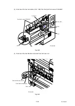
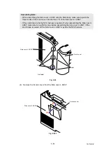
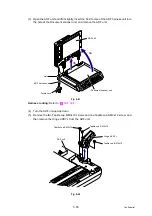
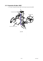
(3) Remove the three Taptite cup S M3x6 SR screws, and then remove the USB direct
interface FG harness ASSY and Main shield cover plate ASSY.
Fig. 5-34
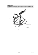
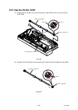
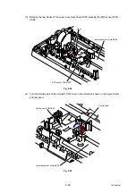
(4) Disconnect the five Connectors (CN16, CN14, CN13, CN11, CN8) from the Main PCB ASSY.
(5) Remove the three Taptite cup S M3x6 SR screws, and then remove the FB FG harness
ASSY, ADF FG harness ASSY and NCU FG harness ASSY 2 from the Main PCB shield plate.
Fig. 5-35
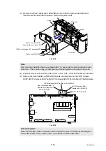
Note:
After removing the Main shield cover plate ASSY, do not set up the main body with the left
side down. The machine may get damaged due to load applied to the paper feed motor.
Assembling Note:
Place the Harness of the Connectors (CN16 and CN14) at the front when assembling the
Connectors (CN16, CN14, CN13, CN11, and CN8) to the Main PCB ASSY.
Main body
Taptite cup S M3x6 SR
Taptite cup S M3x6 SR
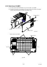
Main shield cover plate ASSY
Hook
Hook
Hook
<Left side>
USB direct interface FG harness ASSY
CN24
CN20
CN27
CN26
CN23
CN22
CN19
CN15
CN10
CN1
CN2
CN3
CN18
CN17
CN16 CN14 CN13
CN11
CN8
CN5
CN6
Main PCB ASSY
Main PCB shield plate
FB FG harness ASSY (Taptite cup S M3x6 SR)
ADF FG harness ASSY
(Taptite cup S M3x6 SR)
NCU FG harness ASSY 2
(Taptite cup S M3x6 SR)
Содержание DCP-9010CN
Страница 11: ...Confidential CHAPTER 1 SPECIFICATIONS ...
Страница 53: ...Confidential CHAPTER 2 THEORY OF OPERATION ...
Страница 90: ...Confidential CHAPTER 3 ERROR INDICATION AND TROUBLESHOOTING ...
Страница 201: ...Confidential CHAPTER 4 PERIODICAL MAINTENANCE ...
Страница 224: ...Confidential CHAPTER 5 DISASSEMBLY AND ASSEMBLY ...
Страница 440: ...Confidential CHAPTER 6 ADJUSTMENTS AND UPDATING OF SETTINGS REQUIRED AFTER PARTS REPLACEMENT ...
Страница 446: ...6 5 Confidential 10 Alert warning message appears click Continue Anyway to proceed ...
Страница 456: ...Confidential CHAPTER 7 SERVICE FUNCTIONS ...
Страница 464: ...7 6 Confidential For color scanning Fig 7 2 ...
Страница 487: ...7 29 Confidential Cover page sample Fig 7 13 End page sample Fig 7 14 ...
Страница 492: ...7 34 Confidential Color registration adjustment chart Fig 7 16 ...
Страница 496: ...7 38 Confidential LED test pattern M68_L Fig 7 18 ...
Страница 498: ...7 40 Confidential Fig 7 19 ...
Страница 500: ...7 42 Confidential Color test pattern Fig 7 20 MCYK Y C K M YCMK_ _A ...
Страница 518: ...Confidential CHAPTER 8 CIRCUIT DIAGRAMS WIRING DIAGRAM ...
Страница 520: ...Confidential 8 1 1 CIRCUIT DIAGRAMS High voltage Power Supply PCB Circuit Diagram SYS HITEK SPH 8N35 1 3 ...
Страница 521: ...Confidential 8 2 High voltage Power Supply PCB Circuit Diagram SYS HITEK SPH 8N35 2 3 ...
Страница 522: ...Confidential 8 3 High voltage Power Supply PCB Circuit Diagram SYS HITEK SPH 8N35 3 3 ...
Страница 523: ...Confidential 8 4 High voltage Power Supply PCB Circuit Diagram MURATA MPH3316 1 3 ...
Страница 524: ...Confidential 8 5 High voltage Power Supply PCB Circuit Diagram MURATA MPH3316 2 3 ...
Страница 525: ...Confidential 8 6 High voltage Power Supply PCB Circuit Diagram MURATA MPH3316 3 3 ...
Страница 526: ...Confidential 8 7 Low voltage Power Supply PCB Circuit Diagram 100V ...
Страница 527: ...Confidential 8 8 Low voltage Power Supply PCB Circuit Diagram 200V ...
Страница 528: ...Confidential 8 9 NCU PCB Circuit Diagram USA Canada ...
Страница 529: ...Confidential 8 10 NCU PCB Circuit Diagram Europe Asia Oceania China ...
Страница 530: ...Confidential 8 11 NCU PCB Circuit Diagram South Africa Gulf ...
Страница 531: ...Confidential 8 12 2 WIRING DIAGRAM Wiring Diagram 1 2 ...
Страница 532: ...Confidential 8 13 Wiring Diagram 2 2 ...
Страница 590: ...Confidential APPENDIX 3 SERIAL NUMBERING SYSTEM ...
Страница 592: ...App 3 2 Confidential Serial number of the LED ASSY Print position Fig App 3 4 Serial number ...
Страница 593: ...Confidential APPENDIX 4 SCREW CATALOGUE ...
Страница 595: ...Confidential APPENDIX 5 REFERENCES ...
Страница 597: ...Confidential APPENDIX 6 GLOSSARY ...


