Brother DCP-7090 Скачать руководство пользователя страница 119

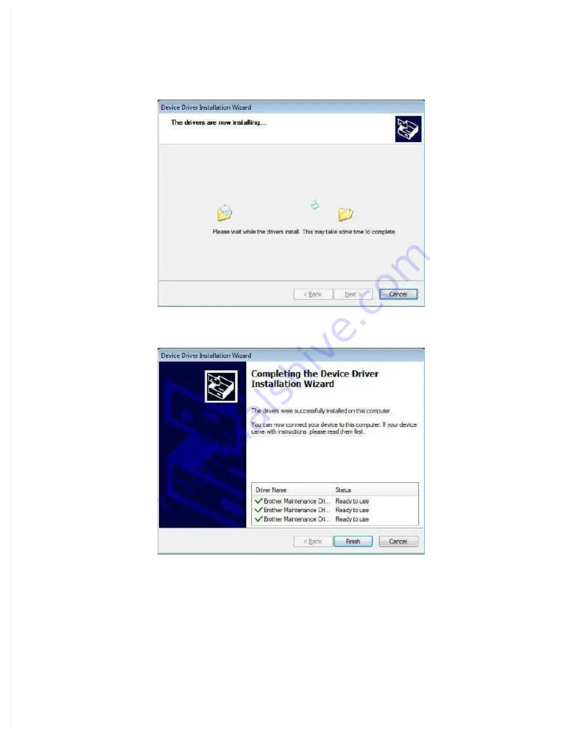
The following screen is displayed during installation.

(4) Wait for the following screen to appear and click [Finish].

(5) Plug the AC cord of the machine into an electrical outlet.

(6) Enter the maintenance mode.

(Refer to “1.1  How to Enter Maintenance Mode” in Chapter 5.)

(7) Connect the machine to your computer using a USB cable and the installation will be

performed automatically.

Содержание DCP-7090

Страница 1: ...W DCP L2510D L2511D L2512D L2530DW DCP L2531DW L2532DW L2535D L2535DW DCP L2531DW L2532DW L2535D L2535DW DCP L2536D L2537DW L2550DN L2550DW DCP L2536D L2537DW L2550DN L2550DW DCP L2551DN L2551DW L2552DN DCP L2551DN L2551DW L2552DN HL L2390DW L2395DW HL L2390DW L2395DW MFC 7390 7490D 7890DN 7895DW MFC 7390 7490D 7890DN 7895DW MFC B7700D B7715DW B7720DN MFC B7700D B7715DW B7720DN MFC L2690DW L2710DN...

Страница 2: ...Alliance Inc in the United States and other countries Unauthorized use the United States and other countries Unauthorized use is strictly prohibited is strictly prohibited Each company whose software title is mentioned in this manual has a Software License Agreement Each company whose software title is mentioned in this manual has a Software License Agreement specific to its proprietary programs s...

Страница 3: ...7 Brother Industries Ltd All rights reserved This product includes software developed by the following vendors This product includes software developed by the following vendors 1983 1998 PACIFIC SOFTWORKS INC ALL RIGHTS RESERVED 1983 1998 PACIFIC SOFTWORKS INC ALL RIGHTS RESERVED 2008 Devicescape Software Inc All rights reserved 2008 Devicescape Software Inc All rights reserved This product includ...

Страница 4: ...n Drawi Drawing ng 2 5 2 5 2 1 1 2 1 1 Printe Printer part r part 2 5 2 5 2 1 2 2 1 2 Scanne Scanner part r part 2 7 2 7 2 2 2 2 Paper Feedi Paper Feeding ng 2 9 2 9 2 2 1 2 2 1 Printe Printer part r part 2 9 2 9 2 2 2 2 2 2 Scanne Scanner part r part 2 11 2 11 2 3 2 3 Operat Operation of ion of Each Pa Each Part and rt and Locat Location of ion of Parts Parts 2 12 2 12 2 4 2 4 Block Dia Block Dia...

Страница 5: ...nit P nit Problem roblems s 2 101 2 101 4 7 1 4 7 1 New New toner toner not d not detecte etected d 2 101 2 101 4 7 2 4 7 2 Toner Toner cartri cartridge n dge not d ot detected etected 2 101 2 101 4 7 3 4 7 3 Toner Toner replace replacement ment messag message di e displaye splayed on d on LCD LCD is n is not c ot cleared leared 2 102 2 102 4 7 4 4 7 4 Drum er Drum error ror 2 102 2 102 4 7 5 4 7 ...

Страница 6: ...ara Preparation tion 3 23 3 23 9 2 9 2 Cord hook Cord hook 3 25 3 25 9 3 9 3 Back cover Back cover 3 26 3 26 9 4 9 4 Outer ch Outer chute ASSY ute ASSY 3 27 3 27 9 5 9 5 Front cov Front cover ASSY Support fla er ASSY Support flap p 3 28 3 28 9 6 9 6 Side cover R Side cover R 3 31 3 31 9 7 9 7 Fuser cover Fuser cover 3 32 3 32 9 8 9 8 Inner chu Inner chute ASSY te ASSY 3 33 3 33 9 9 9 9 Si Side c d...

Страница 7: ...84 9 27 Roller holder ASSY 3 85 9 28 Main PCB ASSY 3 86 9 29 T1 clutch Registration clutch 3 87 9 30 Frame L unit 3 90 9 31 Paper feed motor Paper feed motor flat cable 3 93 9 32 Fuser gear 64R 36R 3 95 9 33 Toner sensor PCB ASSY Only for models with Toner box 3 96 9 34 Front cover sensor 3 97 9 35 Eject sensor PCB ASSY 3 98 9 36 Registration front rear actuator holder ASSY 3 100 9 37 Paper feed r...

Страница 8: ...code 03 5 5 1 3 3 ADF performance test Function code 08 5 6 1 3 4 Print quality test pattern Function code 09 5 7 1 3 5 Set worker switches WSW and print worker switch setting data Function code 10 11 5 8 1 3 6 Check LCD operation Function code 12 5 11 1 3 7 Check control panel key operation Function code 13 5 13 1 3 8 Display software version Function code 25 5 15 1 3 9 Check sensor operation Fun...

Страница 9: ...28 Display machine error code Function code 82 5 57 1 3 29 Send communication log information to telephone line Function code 87 5 58 1 3 30 Reset irregular power supply detection counter of low voltage power supply PCB Function code 88 5 58 1 3 31 Quit maintenance mode Function code 99 5 58 2 OTHER SERVICE FUNCTIONS 5 59 2 1 Drum Cleaning 5 59 2 2 Print Communication Error List 5 61 2 3 Resetting...

Страница 10: ...roduct as they may touch dangerous voltage points or short out parts DO NOT handle the plug with wet hands Doing this might cause an electrical shock DO NOT use this product during a thunderstorm There may be a remote risk of an electrical shock from lightning Always make sure the plug is fully inserted DO NOT use the product or handle the cord if the cord has become worn or frayed DO NOT allow th...

Страница 11: ...xtension cord DO NOT put toner cartridges or a toner cartridge and drum unit assembly into a fire or places susceptible to fire It could explode resulting in injuries DO NOT use flammable substances any type of spray or an organic solvent liquid containing alcohol or ammonia to clean the inside or outside of the product Doing so could cause a fire or electrical shock Instead use only a dry lint fr...

Страница 12: ...use this product near water or locations that may become wet for example near a bathtub wash bowl kitchen sink or washing machine in a wet basement or near a swimming pool 2 Avoid using this product during a thunderstorm There may be a remote risk of an electric shock from lightning 3 DO NOT use this product to report a gas leak in the vicinity of the leak 4 Use only the power cord provided with t...

Страница 13: ...einheit darf nicht geöffnet werden da sonst Laserstrahlen austreten können Additional Information When servicing the optical system of the machine be careful not to place a screwdriver or other reflective object in the path of the laser beam Be sure to take off any personal accessories such as watches and rings before working on the machine A reflected beam though invisible can permanently damage ...

Страница 14: ...d after July 23 2001 the REN for this product is part of the product identifier that has the format US AAAEQ TXXXX The digits represented by are the REN without a decimal point e g 06 is a REN of 0 6 For earlier products the REN is separately shown on the label If this equipment causes harm to the telephone network the telephone company will notify you in advance that temporary discontinuance of s...

Страница 15: ...nt may not be used on coin service lines provided by the telephone company or connected to party lines Brother cannot accept any financial or other responsibilities that may be the result of your use of this information including direct special or consequential damages There are no warranties extended or granted by this document A grounded plug should be plugged into a grounded AC power outlet aft...

Страница 16: ...22 4 x 17 1 580 x 517 x 434 mm 22 8 x 20 4 x 17 1 except for MFC B7720DN 580 x 570 x 434 mm 22 8 x 22 4 x 17 1 MFC B7720DN 580 x 517 x 434 mm 22 8 x 20 4 x 17 1 MachineDimensions W x D x H 481 x 398 5 x 318 5 mm 18 9 x 15 7 x 12 5 410 x 398 5 x 318 5 mm 16 1 x 15 7 x 12 5 except for MFC B7720DN 481 x 398 5 x 318 5 mm 18 9 x 15 7 x 12 5 MFC B7720DN 410 x 398 5 x 318 5 mm 16 1 x 15 7 x 12 5 Weight w...

Страница 17: ...0 4 x 17 1 608 x 570 x 434 mm 23 9 x 22 4 x 17 1 MachineDimensions W x D x H 410 x 398 5 x 318 5 mm 16 1 x 15 7 x 12 5 481 x 426 5 x 318 5 mm 18 9 x 16 8 x 12 5 481 x 398 5 x 318 5 mm 18 9 x 15 7 x 12 5 410 x 398 5 x 318 5 mm 16 1 x 15 7 x 12 5 410 x 426 5 x 318 5 mm 18 9 x 16 8 x 12 5 Weight w Carton 14 7 kg 32 5 lb MFC L2730DW for US EU OCE 14 9 kg 32 8 lb forMFC L2732DW TBD MFC L2730DW for LTN ...

Страница 18: ... DCP L2551DW HL L2395DW MFC 7390 MFC 7490D MFC B7700D MFC L2715D MFC L2716D MFC B7720DN MFC L2710DN MFC L2712DN Wired network Network node type NC 9300h type2 N A NC 9300h type2 Wireless network Network node type NC 8800w type2 N A Model MFC L2690DW MFC B7715DW MFC L2710DW MFC L2712DW MFC L2713DW MFC L2715DW MFC L2716DW MFC L2717DW MFC 7890DN MFC L2730DW MFC L2732DW MFC 7895DW MFC L2750DW MFC L275...

Страница 19: ...o take voltage measurements with the power switched on take the greatest of care not to receive an electric shock power switched on take the greatest of care not to receive an electric shock 2 2 When con When connectin necting or discon g or disconnectin necting cable co g cable connector nnectors make su s make sure that you h re that you hold the old the connector body and not the cables connect...

Страница 20: ...set to invalid to serve invalid to serve the needs of the needs of customers Ask sales customers Ask sales representative if this is the case before performing the check representative if this is the case before performing the check Warning Warning DO NOT DO NOT use any flammable spray or flammable solvent such as alcohol use any flammable spray or flammable solvent such as alcohol benzine or thin...

Страница 21: ...talled corr alled correctly ectly Others Others 1 1 Co Cond nden ensa sati tion on When the machine is moved from a cold place into a warm room condensation may occur When the machine is moved from a cold place into a warm room condensation may occur inside the machine causing various inside the machine causing various problems as listed below problems as listed below Conden Condensation on the su...

Страница 22: ...O NOT DO NOT use any flammable spray or flammable solvent such as alcohol benzine use any flammable spray or flammable solvent such as alcohol benzine or thinner to clean the machine or thinner to clean the machine DO NOT DO NOT use these articles near the machine use these articles near the machine ...

Страница 23: ... r a ac ct tu ua at to or r Front side Front side Registration front actuator Registration front actuator Manual feed Manual feed slot slot Paper dust Paper dust cleaning roller cleaning roller Paper feed Paper feed actuator actuator Paper pick up roller Paper pick up roller Plate Plate Duplex paper feed roller Duplex paper feed roller Pressure roller Pressure roller Duplex tray Duplex tray Heat r...

Страница 24: ...eed Paper feed actuator actuator Paper pick up roller Paper pick up roller Paper empty actuator Paper empty actuator Plate Plate Duplex paper feed roller Duplex paper feed roller Pressure roller Pressure roller Duplex tray Duplex tray Heat roller Heat roller Back cover Back cover Registration roller Registration roller Separation Separation roller roller Separation Separation pad pad Eject actuato...

Страница 25: ... Document stopper Document stopper Scanner glass Scanner glass Document sponge Document sponge Document eject roller Document eject roller Document eject pinch roller Document eject pinch roller Document pick up roller Document pick up roller Document detection actuator Document detection actuator First side CIS unit First side CIS unit First side First side document hold document hold Document fe...

Страница 26: ...ment stopper Scanner glass Document sponge Document eject roller Document eject pinch roller Document pick up roller Document detection actuator First side CIS unit First side document hold Document feed roller 2 Document pinch roller 2 Document scanning position actuator Second side document hold Second side CIS unit Scanner glass strip First side CIS glass Scanner glass strip Second side CIS gla...

Страница 27: ...2 9 Confidential 2 2 Paper Feeding 2 2 1 Printer part Manual feed slot models Fig 2 5 Eject to output tray Feed from manual feed slot Duplex path Eject to back side Back side Front side ...

Страница 28: ...2 10 Confidential MP models Fig 2 6 Feed from MP tray Eject to back side Back side Front side ...

Страница 29: ...2 11 Confidential 2 2 2 Scanner part Fig 2 7 Document feed path ...

Страница 30: ...oller 2 switching Detects paper jam in the rear section of the machine Detects open fuser cover Eject roller 1 Feeds the paper ejected from the fuser unit to eject roller 2 Eject roller 2 Eject the paper to the face down output tray In the case of the 2 sided printing after the front of the sheet is printed and the paper is fed up to a certain point eject roller 2 rotates conversely and the paper ...

Страница 31: ...on of the registration roller for the paper alignment adjustment MP solenoid Presses the MP paper pick up roller against the paper when feeding from the MP tray Part name Operation T1 clutch New toner sensor PCB ASSY Toner box relay PCB ASSY 1 MP relay PCB ASSY 2 Registration clutch Registration rear sensor Registration front sensor Paper feed sensor PCB ASSY Toner box solenoid 1 Eject sensor PCB ...

Страница 32: ... 03 Turn the power off and then back on again Cannot detect the lock signal of the polygon motor for the laser unit second time 0300 2 47 Print Unable 04 Turn the power off and then back on again BD sensor failure second time 0401 2 48 Print Unable 05 Turn the power off and then back on again Detected the fuser unit temperature error 0501 2 49 0502 2 49 0503 2 49 0504 2 49 0505 2 49 0506 2 49 0508...

Страница 33: ...An error occurred while initializing the modem D100 2 70 Print Unable E0 Turn the power off and then back on again An error occurred in the ROM check sum E000 2 71 Print Unable E1 Turn the power off and then back on again Program error E100 2 71 Print Unable E5 Turn the power off and then back on again An error occurred during access to the DRAM in the main PCB ASSY E500 2 71 Print Unable E6 Turn ...

Страница 34: ...ient in the scanned first side data AD00 2 67 Scan Unable A9 Turn the power off and then back on again A scanning error occurred while processing the scanned image A900 2 67 Scan Unable AF Turn the power off and then back on again Home position is still being detected even after the first side CIS unit was moved AF00 2 68 Scanner Error BB A white level not within the standard was scanned when func...

Страница 35: ...er or larger than the specified size in duplex printing mode 8A01 2 61 Sizemismatch Reload correct paper Paper size is not set as A4 Letter Legal Folio when receiving fax or printing a list report 8E01 2 62 Detected that the size of paper set in the paper tray was over 10 mm shorter than paper size set in the machine during faxing or printing a list or report 8E02 2 62 Reload correct paper in MP T...

Страница 36: ...tialisation Failed Remove any material which is on the touchscreen An error occurred while initializing the touch panel D800 2 71 Tray removed Change the settings Paper tray is open 4 14 5 Wrong Paper Size MP Reload correct paper in MP Tray or press Retry MP tray ran out of paper and the paper tray alternatively chosen has paper in different size when the paper used for copy was from the MP tray a...

Страница 37: ...printing is started before the registration of printing in the engine 8903 2 61 The back cover sensor detected the open state during 2 sided printing after the registration of printing in the engine 8904 2 61 Error message Description Error codes Refer to Upper line Lower line ...

Страница 38: ...GN line 33 digits or longer or non numeric characters 4 13 2 17 07 No response from the caller in receiving 4 13 2 1C 01 Detected that access to the NGN line was not authorized T38 403 Forbidden 4 13 3 1C 02 No file or folder directory found as a result of search via the NGN line T38 404 Not Found 4 13 3 1C 03 Remote station does not support the NGN line T38 488 Not Acceptable Here 4 13 3 1C 04 SI...

Страница 39: ...k Replace the toner box with a new toner box again If the machine is on the uneven surface place it on a level surface Step Cause Remedy 1 Connection failure of the new toner sensor PCB harness Reconnect the new toner sensor PCB harness 2 New toner actuator coming off or caught in some sections of the machine Reattach the new toner actuator 3 New toner sensor failure Replace the new toner sensor P...

Страница 40: ...ness 2 Front cover failure Replace the front cover 3 Front cover sensor failure Replace the front cover sensor 4 Main PCB failure Replace the main PCB ASSY Step Cause Remedy 1 Eject actuator coming off or caught in some sections of the machine Reattach the eject actuator 2 Fuser cover attachment failure Reattach the fuser cover 3 Connection failure of the eject sensor PCB harness Reconnect the eje...

Страница 41: ...y PCB ASSY 3 Main PCB failure Replace the main PCB ASSY Step Cause Remedy 1 New toner box actuator coming off or caught in some sections of the machine Reattach the new toner box actuator 2 New toner box sensor failure Replace the high voltage power supply PCB ASSY 3 Main PCB failure Replace the main PCB ASSY Step Cause Remedy 1 Dirt on the electrodes of the drum unit and those of the machine Clea...

Страница 42: ... Electrodes location of main body Fig 2 12 Electrodes location of the drum unit and process unit Fig 2 13 ...

Страница 43: ... 2 Fuser unit thermistor failure Replace the fuser unit 3 Main PCB failure Replace the main PCB ASSY Step Cause Remedy 1 Connection failure of a fuser unit harness Reconnect the fuser unit harness 2 Connection failure of the eject sensor PCB harness Reconnect the eject sensor PCB harness 3 Fuser unit failure Replace the fuser unit 4 Eject sensor PCB failure Replace the eject sensor PCB ASSY 5 Low ...

Страница 44: ... on the high voltage power supply PCB terminal Clean the high voltage power supply PCB terminal 3 High voltage power supply PCB failure Replace the high voltage power supply PCB ASSY 4 Main PCB failure Replace the main PCB ASSY Step Cause Remedy 1 The power supply waveform is incorrect Install a voltage stabilizer in the power supply part Step Cause Remedy 1 Foreign object inside the machine Remov...

Страница 45: ...rform drum cleaning Refer to 2 1 Drum Cleaning in Chapter 5 3 Clogged filter Clean the filter 4 Scratch or dirt on the fuser unit Replace the fuser unit 5 High voltage power supply PCB failure Replace the high voltage power supply PCB ASSY Note Image defects which appear periodically may be caused by failure of rollers Refer to the table below and determine the cause based on the pitch at which de...

Страница 46: ...Fig 2 14 P2 73 to clean the paper dust cleaning roller 2 Dirt on the exposure drum Perform drum cleaning Refer to 2 1 Drum Cleaning in Chapter 5 3 Clogged filter Clean the filter 4 Scratch or dirt on the fuser unit Replace the fuser unit 5 High voltage power supply PCB failure Replace the high voltage power supply PCB ASSY Note Image defects which appear periodically may be caused by failure of ro...

Страница 47: ...after printing multiple sheets of paper Refer to How to clean the drum unit to remove the dirt from the exposure drum using a cotton applicator Replace the drum unit with a new one Replace the toner cartridge with a new one Step Cause Remedy 1 A ground wire or ground plate installation failure Grounding is not performed correctly Retighten the screws of each ground wire or ground plate Repair the ...

Страница 48: ...mark in drum region 2 Fig 2 21 3 Turn the edge of the drum unit towards you while looking at the drum surface to find the mark Fig 2 22 4 Wipe the surface of the drum gently with a dry cotton swab until the mark or foreign material on the surface comes off Fig 2 23 Note Do not clean the exposure drum surface with anything sharp like a ball pointed pen ...

Страница 49: ...ean the drum unit to remove the dirt from the exposure drum using a cotton applicator Replace the drum unit with a new one Replace the toner cartridge with a new one Step Cause Remedy 1 Dirty charge electrodes Clean the electrodes of the drum unit and those of the machine Refer to Fig 2 13 P2 56 and Fig 2 12 P2 56 2 Dirt on the exposure drum Perform drum cleaning Refer to 2 1 Drum Cleaning in Chap...

Страница 50: ...the usage environment of the machine Using the machine in hot humid or cold dry conditions can cause this problem Check if the acid paper is not used This problem may disappear after printing multiple sheets of paper Replace the toner cartridge with a new one Replace the drum unit with a new one Step Cause Remedy 1 Dirt on the electrodes of the toner cartridge and those of the machine Clean the el...

Страница 51: ... t 7 7 P Pa an ne el l P PC CB B A AS SS SY Y f fa ai il lu ur re e R Re ep pl la ac ce e t th he e p pa an ne el l P PC CB B A AS SS SY Y 8 8 Low voltage power supply Low voltage power supply PCB failure PCB failure Replace the low voltage power supply PCB Replace the low voltage power supply PCB ASSY ASSY 9 9 M Ma ai in n P PC CB B f fa ai il lu ur re e R Re ep pl la ac ce e t th he e m ma ai in...

Страница 52: ...on failure of the Connection failure of the toner box relay PCB harness toner box relay PCB harness Models with toner box Models with toner box Reconnect the toner box relay PCB harness Reconnect the toner box relay PCB harness 5 5 New toner sensor PCB New toner sensor PCB failure failure Models without toner box Models without toner box Replace the new toner sensor Replace the new toner sensor PC...

Страница 53: ...w toner sensor PCB failure failure Models without toner box Models without toner box Replace the new toner sensor Replace the new toner sensor PCB ASSY PCB ASSY 6 6 New toner box sensor PCB New toner box sensor PCB failure failure Models with toner box Models with toner box Replace the new toner box sensor PCB Replace the new toner box sensor PCB ASSY ASSY 7 7 T Toner box relay oner box relay PCB ...

Страница 54: ...ge power supply PCB Replace the low voltage power supply PCB ASSY ASSY 7 7 F Fu us se er r u un ni it t f fa ai il lu ur re e R Re ep pl la ac ce e t th he e f fu us se er r u un ni it t 8 8 M Ma ai in n P PC CB B f fa ai il lu ur re e R Re ep pl la ac ce e t th he e m ma ai in n P PC CB B A AS SS SY Y Note Note Turn the po Turn the power swit wer switch OFF and then ON agai ch OFF and then ON aga...

Страница 55: ...t the prin e print dat t data is no a is not dama t damaged ged 4 10 2Full memory 4 10 2Full memory User Check User Check Prin Print the acc t the accumu umulat lated dat ed data a Reduce Reduce the amou the amount or res nt or resolution olution of the da of the data ta S St te ep p C Ca au us se e R Re em me ed dy y 1 1 M Ma ai in n P PC CB B f fa ai il lu ur re e R Re ep pl la ac ce e t th he e...

Страница 56: ...upper limit in the document tray document tray S St te ep p C Ca au us se e R Re em me ed dy y 1 1 Document detection actuator Document detection actuator coming off coming off Reattach the document detection actuator Reattach the document detection actuator 2 2 Connection failure of the ADF Connection failure of the ADF motor harness motor harness Reconnect the ADF motor harness Reconnect the ADF...

Страница 57: ...off Reattach the document pinch roller 1 3 Damaged ADF drive gear Replace the ADF unit 4 Main PCB failure Replace the main PCB ASSY Step Cause Remedy 1 Foreign object inside the ADF Remove the foreign object 2 Document scanning position actuator coming off Reattach the document scanning position actuator 3 Document pinch roller 2 coming off Reattach the document pinch roller 2 4 Connection failure...

Страница 58: ...in the ADF document eject path Remove the foreign object 2 Document pinch roller coming off Reattach the document pinch roller 3 Abrasion of document eject roller Replace the ADF unit 4 Main PCB failure Replace the main PCB ASSY Step Cause Remedy 1 Abrasion of document separate roller Replace the document separate roller ASSY 2 Abrasion of document feed roller Replace the ADF unit Step Cause Remed...

Страница 59: ...nner glass strip Clean the document hold Step Cause Remedy 1 Incorrect white level correction data Execute Acquire white level data Function code 55 2 First or second side CIS unit failure Replace the first or second side CIS unit 3 Main PCB failure Replace the main PCB ASSY Light 2 108 Faultyregistration 2 109 Dark 2 109 Completely blank 2 110 All black 2 110 Vertical streaks 2 111 White streaks ...

Страница 60: ...1 Deviation of the scanning start position Execute Fine adjustment of scan start position Function code 54 2 Document scanning position actuator caught in some sections of the machine Reattach the document scanning position actuator User Check Check that the contrast setting is not too dark Clean the document hold Step Cause Remedy 1 Incorrect white level correction data Execute Acquire white leve...

Страница 61: ...or second side CIS unit failure Replace the first or second side CIS unit 4 Main PCB failure Replace the main PCB ASSY User Check Install all the latest firmwares Step Cause Remedy 1 Incorrect white level correction data Execute Acquire white level data Function code 55 2 First or second side CIS flat cable failure Replace the first or second side CIS flat cable 3 First or second side CIS unit fai...

Страница 62: ...on scanner glass Replace the document scanner unit 5 Scratch on second side scanner glass strip Replace the ADF unit User Check Clean the scanner glass or first side second side scanner glass strip Clean the document hold Step Cause Remedy 1 Dirt inside of scanner glass Clean the inside of the scanner glass 2 Dirt inside of first side second side scanner glass strip Clean the inside of the first s...

Страница 63: ...cument sponge Replace the document scanner unit User Check Clean the scanner glass or first side second side scanner glass strip Step Cause Remedy 1 Incorrect white level correction data Execute Acquire white level data Function code 55 2 First or second side CIS unit failure Replace the first or second side CIS unit 3 Main PCB failure Replace the main PCB ASSY ...

Страница 64: ...2 PACKING Fig 3 1 Option carton Carton Polystyrene pad ASSY Spacer carton Option carton TBOX ...

Страница 65: ...0 Taptite bind B M4x12 Screw cup M3x8 Screw cup M3x6 Taptite cup S M3x6 SR Taptite cup S M3x8 SR Taptite cup S Screw cup Taptite cup B Taptite pan B Taptite bind B Taptite pan B M4x14 Screw pan Screw pan S P washer Taptite cup B M3x10 Taptite cup B M3x8 Screw bind Screw bind M3x4 Screw pan M4x8 ...

Страница 66: ...models with ADF Taptite cup B M3x10 1 0 5 0 1 5 1 Upper document chute For models with ADF Taptite cup B M3x10 6 0 5 0 1 5 1 ADF ground harness For models with ADF Screw cup M3x6 black 1 Hinge arm L For models without ADF Taptite cup B M3x10 3 0 5 0 1 5 1 Hinge arm R For models without ADF Taptite cup B M3x10 3 0 5 0 1 5 1 Panel unit Taptite cup B M3x10 4 0 5 0 1 5 1 Shield plate cover Touch panel...

Страница 67: ...ite bind B M4x12 11c for securing the registration chute 1 0 8 0 1 8 1 Taptite cup S M3x8 SR 11d for securing the laser L FG plate 1 0 8 0 1 8 1 Taptite bind B M4x12 12a 2 0 8 0 1 8 1 Taptite cup S M3x8 SR 12b 2 0 8 0 1 8 1 Flat cable guide Taptite bind B M4x12 1 0 8 0 1 8 1 Laser L FG plate Screw pan S P washer M3x12DB 1 0 5 0 1 5 1 Motor drive sub ASSY Taptite bind B M4x12 3 0 8 0 1 8 1 Taptite ...

Страница 68: ...Fuser gear 64R 36R Fig 3 4 Lubricating oil type Maker name Lubrication point Quantity of lubrication BDX313 A Kanto Kasei Hinge ASSY L 9 places 2 0 mm dia ball FLOIL BG 10KS Kanto Kasei Fuser gear 64R 36R 3 places 1 5 to 2 0 mm dia ball ...

Страница 69: ...off 1 D00AHW Ejector gear 16 15 8 D00HHK Gear 70R DEV 2 LY9006 Ejector gear 33 9 D00HHM Clutch DEV NON toner box 3 LY9005 Ejector gear 40 10 D00HHL Gear 55 DEV 4 D00ALK Gear oneway 35L 22 fuser 11 D00EFZ Gear DEV idle 24 5 D00ALM Clutch fuser 12 D00AKE Gear 115L 30L drum 6 D00ALL Gear oneway 20 fuser 13 D00AH4 Gear 47R DX 7 D00ALH Gear 64R 36R fuser 1 2 3 7 4 5 6 8 9 10 12 13 11 1 2 3 5 4 6 7 8 9 ...

Страница 70: ...me L faces up Otherwise all gears come off 14 D00EGI Gear toner box idle 32 19 D00CXT Gear 23R PF 15 D00CUB Sector gear toner box 20 D00AK9 Gear 38L PF 16 D00AM4 Gear 68R drum idle 21 D00AK8 Gear 28R 18 PF 17 D00AKA Gear 50L PF 22 D00AK7 Gear 34L PF 18 D00CXU Clutch PF 23 LY9088 Feeder gear 34 17 18 19 16 15 14 20 21 22 23 17 16 15 14 18 19 20 21 23 22 ...

Страница 71: ...cond side CIS flat cable from the Main PCB ASSY Fig 3 26 Harness routing Refer to 2 ADF unit 3 Document scanner unit Note After disconnecting flat cables check that each cable is not damaged at its end or short circuited When connecting flat cables do not insert them at an angle After insertion check that the cables are not at an angle ADF ground harness Screw cup M3x8 black FB ground harness Main...

Страница 72: ...arness unit from each Hole on the Joint cover Fig 3 27 Harness routing Refer to 2 ADF unit 3 Document scanner unit Assembling Note If you replaced the Document scanner unit refer to 5 IF YOU REPLACE THE ADF UNIT FIRST SIDE CIS UNIT SECOND SIDE CIS UNIT OR DOCUMENT SCANNER UNIT in Chapter 4 to configure settings Hook ADF FFC holder 30 Document scanner unit Document scanner unit Document scanner mot...

Страница 73: ...rew from the Hinge ASSY L Fig 3 28 Fig 3 29 Assembling Note Attach the Panel flat cable the First side CIS flat cable and the Second side CIS flat cable to the ADF FFC holder as shown in the figure below Hinge ASSY L Taptite bind B M4x12 black ADF FFC holder First side CIS flat cable Panel flat cable Second side CIS flat cable First side CIS flat cable Second side CIS flat cable ADF FFC holder Pan...

Страница 74: ...lat cable Fig 3 30 Harness routing Refer to 2 ADF unit Fig 3 31 Assembling Note If you replaced the ADF unit refer to 5 IF YOU REPLACE THE ADF UNIT FIRST SIDE CIS UNIT SECOND SIDE CIS UNIT OR DOCUMENT SCANNER UNIT in Chapter 4 to configure settings Attach the FFC holder ASSY to the ADF sensor harness unit and the Second side CIS flat cable as shown in the figure below Hinge R FFC holder ASSY Hook ...

Страница 75: ... B M3x10 screw to remove the Hinge R support and the Hinge R from the Hinge arm R 8 Remove the three Taptite cup B M3x10 screws to remove the Hinge arm R from the ADF unit Fig 3 33 Hinge ASSY L Taptite bind B M4x12 ADF unit Hinge R Taptite cup B M3x10 Taptite cup B M3x10 Hinge R support Taptite cup B M3x10 Hinge arm R ADF unit ...

Страница 76: ... 1 Open the ADF cover ASSY Release the two Bosses to remove the ADF cover ASSY from the ADF unit 2 Release the two Bosses to remove the Document stopper from the ADF unit Fig 3 34 Boss Boss Boss Boss ADF cover ASSY Document stopper ADF unit ...

Страница 77: ...o remove the Gear cover from the ADF unit 2 Remove the two Taptite cup B M3x10 screws Release each Hook to remove the ADF front cover from the ADF unit Fig 3 35 ADF unit Hooks Hooks ADF front cover Gear cover Taptite cup B M3x10 Taptite cup B M3x10 ...

Страница 78: ...d side CIS flat cable Only for models with duplex scanning 1 Remove the six Taptite cup B M3x10 screws to remove the Upper document chute from the ADF unit Fig 3 39 Upper document chute ADF unit Taptite cup B M3x10 Taptite cup B M3x10 ...

Страница 79: ...res and pull it out from the Hole of the Document cover 4 Remove the Lower document chute from the Document cover and pull out the Second side CIS flat cable from the Hole of the Document cover Fig 3 40 Harness routing Refer to 2 ADF unit Lower document chute Document cover Ground spring Screw cup M3x6 black ADF ground harness ADF sensor harness unit Second side CIS flat cable Hole Hole ...

Страница 80: ...ok and slide the Second side scanner glass strip in the direction of the arrow 6a Lift the left end of the Second side scanner glass strip to remove it in the direction of the arrow 6b Fig 3 41 Second side scanner glass strip Hook 6a 6b Second side CIS flat cable Lower document chute ...

Страница 81: ...IS spacer R and the CIS spacer F from the Second side CIS unit Fig 3 42 9 Pull out the Second side CIS flat cable from the Hole and the Flat core and remove it from the Lower document chute Fig 3 43 Lower document chute CIS spacer F CIS spacer R Second side CIS unit Second side CIS flat cable Lower document chute Hole Second side CIS flat cable Flat core ...

Страница 82: ...CIS flat cable at the positions described below 45 3 5 1 Mountain fold Valley fold 8 The adhesive range on Reinforcing plate Reinforcing plate 45 4 2 6 2 Main PCB side Second side CIS side Reinforcing plate 15 Reinforcing plate 4 1 1 1 3 1 ...

Страница 83: ...9 12 Document cover ASSY For models without ADF 1 Release the Hooks of the Hinge L and the Hinge R to remove the Document cover ASSY by lifting it up Fig 3 45 Document cover ASSY Hooks Hinge L Hinge R ...

Страница 84: ...L and the Hinge L from the Document cover ASSY 3 Remove the three Taptite cup B M3x10 screws to remove the Hinge arm R and the Hinge R from the Document cover ASSY Fig 3 46 Taptite cup B M3x10 Taptite cup B M3x10 Hinge arm R Hinge arm L Document cover ASSY Hinge L Hinge R ...

Страница 85: ...models without Toner box and the LVPS harness from the Holes Fig 3 91 Harness routing Refer to 10 Frame L unit Manual feed models Assembling Note When assembling the Frame L unit make sure that the Chute ground plate is above the Main PCB FG plate 2 Taptite cup S M3x8 SR 11d Taptite cup S M3x8 SR 12b Taptite bind B M4x12 12a Frame L unit Taptite bind B M4x12 11c Registration chute Taptite cup S M3...

Страница 86: ...move the Motor drive sub ASSY from the Frame L unit Fig 3 92 Harness routing Refer to 10 Frame L unit Manual feed models Assembling Note Be careful not to bend the Laser L FG plate Attach the Motor drive sub ASSY to the Frame L unit while the Develop joint link is pushed Pull the Develop joint link back before tightening the screws for the Motor drive sub ASSY Failure to follow the procedure above...

Страница 87: ...d motor Assembling Note If you removed the Motor drive sub ASSY while the Fuser unit was attached on the machine remove the Fuser unit once refer to 9 18 Fuser unit and reattach it after attaching the Motor drive sub ASSY The Conductive leaf spring of the Fuser unit may be deformed by the Calking shaft If they are not in contact properly a ghost may occur in the printed image Fuser unit Conductive...

Страница 88: ...9 32 Fuser gear 64R 36R 1 Remove the Fuser gear 64R 36R from the Frame L unit Fig 3 95 Fuser gear 64R 36R Frame L unit ...

Страница 89: ...evelop joint disk from the Develop joint lift cover Release the Hook of the Develop joint link to remove the Develop joint lift cover 4 Remove the Develop joint link from the Frame L unit 5 Remove the Taptite bind B M3x8 screw to remove the Film and the Toner sensor PCB ASSY Fig 3 96 Harness routing Refer to 10 Frame L unit Manual feed models Taptite bind B M3x8 Taptite bind B M4x12 Hole Develop j...

Страница 90: ...e Holder toner box and the Lift cam guide from the Frame L unit For models with Toner box Remove the two Taptite bind B M4x12 screws and remove the Lift cam guide from the Frame L unit For models without Toner box 4 Release each Hook to remove the Front cover sensor from the Frame L unit Fig 3 97 Gear toner box idle 32 Spring sector gear toner box Sector gear toner box Hook of Holder toner box Hoo...

Страница 91: ...shown in the figure above If you removed the Main shield plate while the Fuser unit was attached on the machine release the Side thermistor harness ASSY and the Center thermistor harness ASSY from the securing fixture of the Frame L unit Then tighten the screw for the Main shield plate and secure each harness in the securing fixture If the Main shield plate is assembled while the Fuser unit is att...

Страница 92: ...or f ay sensor from the Fra rom the Frame L me L unit unit Fig 3 99 Fig 3 99 Harness routing Refer to Harness routing Refer to 10 10 Frame L unit Manual feed models Frame L unit Manual feed models Assembling Note Assembling Note When assemb When assembling the Back cover ling the Back cover duple duplex tray sensor x tray sensor attach it by engagin attach it by engaging the Hooks g the Hooks C of...

Страница 93: ...ection of the arrow A to remove it from the Pin right side of the LVPS shield plate in the direction of the arrow A to remove it from the Pin And then pull it out in the direction of the arrow B to remove it from the machine And then pull it out in the direction of the arrow B to remove it from the machine Fig 3 100 Fig 3 100 Note Note As the Und As the Under bar is eas er bar is easy to bend b y ...

Страница 94: ...3 101 Harness routing Refer to Harness routing Refer to 12 12 T Top side of op side of the registration chute the registration chute 13 13 Frame R unit Frame R unit Assembling Note Assembling Note When atta When attaching the Fra ching the Frame R unit chec me R unit check that the L k that the LVPS FG plate is set to the Fra VPS FG plate is set to the Frame R me R unit unit Taptite cup S M3x6 SR ...

Страница 95: ... After asse After assembling the Regi mbling the Registratio stration front rea n front rear actuator hold r actuator holder ASSY to the Registratio er ASSY to the Registration n chute push the Actuators by fingers and check if they are pushed back by their springs chute push the Actuators by fingers and check if they are pushed back by their springs if the springs are not caught at assembling if ...

Страница 96: ...f the arrow direction of the arrow Remove the Remove the two Feed two Feed roller bushings from the Paper feed roller ASSY roller bushings from the Paper feed roller ASSY 5 5 Relea Release the Hoo se the Hook A to remove the k A to remove the Paper feed s Paper feed sensor PC ensor PCB ASSY B ASSY Release t Release the Paper fe he Paper feed ed sensor harness from the securing fixtures sensor harn...

Страница 97: ...ing tool SvSettingTool exe Copy this file into the temporary folder created on the C drive NET Framework 4 5 2 or later of Microsoft is needed to use SvSettingTool 4 Download utility FILEDG32 EXE Copy this file into the temporary folder created on the C drive 5 Maintenance printer driver MaintenanceDriver zip When the maintenance printer driver is not installed on the computer copy this file into ...

Страница 98: ...ANCE 25 on the LCD and press the OK For keypad models press the 2 and 5 in this order The main firmware version information is displayed on the LCD 3 Press the Start to display the version information of the sub firmware on the LCD and then check the version information For models with touch panel 1 Press and hold the for approximately five seconds while the machine is in the ready state 2 Press t...

Страница 99: ...ing is completed the machine restarts and returns to the ready state automatically 6 Turn OFF the power switch of the machine and then repeat the procedures 1 to 5 to install required firmwares However when the supply PCB is replaced with a new one the machine automatically enters maintenance mode by turning it ON so the procedure 1 to enter the maintenance mode is not necessary 7 Turn OFF the pow...

Страница 100: ... A 7 Enter all or part of the model name in the box B and press the Find a model Series name and model name are displayed in the box C Non touch panel models 1 Press the Menu and then the Start while the machine is in the ready state Then press the four times to enter the maintenance mode Touch panel models 1 Press and holdthe for approximately five seconds while the machine is in the ready state ...

Страница 101: ... screen 12 Click the Get information shown as D The machine maintenance information appears 13 In the maintenance information check that the value in the Laser Adjusted value Video field and the value in the Laser Adjusted value Position field are same as the value entered in procedure 8 14 Click the Cancel shown as M and close the Get information screen 15 Turn OFF the power switch of the machine...

Страница 102: ...ion code 12 What you need to prepare Touch panel models only 1 Touch pen 4 1 Adjusting Touch Panel Function code 61 Touch panel models only Adjust the touch panel as described in 1 3 18 Adjust touch panel Function code 61 in Chapter 5 4 2 Checking LCD Operation Function code 12 Check the LCD operation as described in 1 3 6 Check LCD operation Function code 12 in Chapter 5 ...

Страница 103: ...on code 55 Acquire white level data as described in 1 3 16 Acquire white level data and set CIS scan area Function code 55 in Chapter 5 5 2 Scanning and Printing Check Print a copy of any document with ADF and check if there is any problem on the printed image Check if there is any problem on the ADF and the performance of recording part Check if there is any problem on the document scanner unit a...

Страница 104: ...ight appears on the LCD 3 Press the 2 8 6 and 4 in this order The display shown on the right appears on the LCD and the machine enters into maintenance mode 4 To select any of the maintenance mode functions shown in the 1 2 List of Maintenance Mode Functions use the keypad to enter the maintenance mode function code to be executed For models without touch panel 1 Press the Menu and then the Start ...

Страница 105: ... PTN on the LCD and press the SET or OK PRINTING is displayed on the LCD and the print adjustment test pattern refer to the next page is printed on a sheet of paper 3 Adjust the line so that the width is 10 mm in horizontal vertical direction Press the or to display desired direction on the LCD Horizontal direction MAIN SIZE SET Vertical direction SUB SIZE SET Press the SET or OK SET 0 0 is displa...

Страница 106: ... Print adjustment test pattern Fig 5 11 ...

Страница 107: ...mmunication list information for the past three errors press the 5 5 COM LIST ERR3 is displayed on the LCD To transfer the maintenance information list printed by function code 77 press the 6 6 MNT77LIST is displayed on the LCD 2 Press the SET or OK while either 2 ACTIVITY 3 DOCUMENTS 4 COM LIST NEW 5 COM LIST ERR3 or 6 MNT77LIST is displayed on the LCD ENTER NO SET is displayed on the LCD 3 Enter...

Страница 108: ...machine Fax number of the sender machine Telephone number of the sender machine Transfer date and time Model code Boot ROM information ROM information Serial number Job number to identify the transmission Total number of pages to be transferred Station ID registered in the sender machine Fax number of the sender machine Telephone number of the sender machine Error codes ...

Страница 109: ...ut ADF proceed to the procedure 2 2 0 MAIN 1 TP 2 HP is displayed on the LCD Press the 0 to adjust the main scanning Press the 1 to adjust the vertical scanning Press the 2 to adjust the rear end side of the vertical scanning For duplex scanning models 0 FRONT 1 BACK is displayed on the LCD Press the 0 to adjust the first side Press the 1 to adjust the second side Proceed to the procedure 4 For si...

Страница 110: ...elope thin SELECT ENVTHICK Envelope thick SELECT HAGAKI Postcard LCD Description SELECT SX Single side printing from paper tray SELECT DX Duplex printing from paper tray LCD Description SELECT 1PAGE 1 page printing SELECT CONTINUE Continuous printing LCD Description Replace Toner Replace the toner cartridge and press the Start or Mono Start to release the error Cover is Open Close the Front cover ...

Страница 111: ... Test pattern Fig 5 19 ...

Страница 112: ... the fourth digit starts flashing Press the or to display numbers for the third and fourth digit on the LCD then press the OK 3 Press the Start or Mono Start to save the new setting and PARAMETER INIT is displayed on the LCD The machine then returns to the initial state of maintenance mode Setting by spec code list Note If there is no entry for one minute or longer the machine returns to the initi...

Страница 113: ... Bulgaria 1050 Croatia 1050 Czech 1050 Hungary 1050 Poland 1050 Romania 1050 Slovakia 1050 Slovenia 1050 Others 1050 DCP L2530DW Argentina 0036 Brazil 0042 Chile 0036 Argentina 0036 France Belgium Netherlands 1055 Belgium 1008 France 7004 Netherlands 9004 Germany 0053 Austria 0014 Iberia 1004 Portugal 1004 Spain 1004 Mexico 0046 Pan Nordic 1004 Denmark 1004 Finland 1004 Norway 1004 Sweden 1004 Oth...

Страница 114: ......

Страница 115: ...CHAPTER 7 PERIODICAL MAINTENANCE 1 PERIODICAL REPLACEMENT PARTS There are no parts to be replaced periodically ...

Страница 116: ...on Fig App 1 2 Serial number 6 digit Manufacturing factory No 201 e g 7 2017 A January B February C March D April E May F June G July H August J September K October L November M December Year of manufacture Month of manufacture A 7N 1 1 1 1 0 1 Model number Serial number Serial number label ...

Страница 117: ...Reset Exit appears on the LCD and press the 5 Reboot OK Yes No appears on the LCD Press the to delete the user setting information and return the machine to the ready state For models with touch panel 1 Press the Settings while the machine is in the ready state 2 Press the ALL Settings on the LCD 3 Press the Initial Setup on the LCD 4 Press the Reset on the LCD 5 Press the Machine Reset on the LCD...

Страница 118: ... 10 1 Check that the AC cord of the machine is unplugged from the electrical outlet Disconnect the USB cable that connects the machine with your computer 2 Turn ON your computer 3 Double click Setup exe inside the Brother Maintenance USB Printer folder that was saved in a temporary folder The following screen appears Click the Next button Note Once this installation procedure is carried out for a ...

Страница 119: ...en to appear and click Finish 5 Plug the AC cord of the machine into an electrical outlet 6 Enter the maintenance mode Refer to 1 1 How to Enter Maintenance Mode in Chapter 5 7 Connect the machine to your computer using a USB cable and the installation will be performed automatically ...

Отзывы: