


Polycold Cryochiller
Appendices
Installation and Operation Manual
Appendix D: Remote EMO
Brooks Automation
214072 Revision B
12-7
Remote EMO Connector Wiring
Construct the EMO Remote cable connection following these steps.
•
Select a cable that meets the 16AWG size requirements for pins 3 and 4.
•
Strip the cable conductors as required for the male crimp terminals.
•
Crimp a male terminal onto each conductor in accordance with best practices.
•
Place the connector back shell onto the cable.
•
Insert the conductor male terminals into the wire side of the connector. See
.
•
Thread the connector back shell onto the connector body and tighten firmly.
•
Install the cable clamp to the back shell and tighten so that the cable clamp firmly holds the
cable. Check for proper cable restraint. Adjust the cable clamp as required.
System EMO Connection
4-pin Connector (female pins)
Cable Connector
4-pin Cable Connector (male pins) (Amp CPC-11 - 206429-1)
Cable Terminal Pins
(4) crimp-tail style male pins for 16 to 18AWG wire size.
Cable Size
16AWG wire required for pins 3 and 4
16 to 18AWG for pins 1 and 2
Cable must be less than 15M (50 feet).
EMO Status Connection
(Output)
Pins 1 and 2 give dry contact switch closure output signal to remote
device to monitor compressor contactor on/off.
Closed = contactor on. Open = contactor off
EMO Control Connection
(Input)
Pins 3 and 4 interrupt the compressor contactor circuit.
Switch set or relay contact pair or jumper wire is required for com-
pressor contactor to turn on.
Closed = contactor enabled. Open = contactor disabled
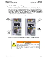
Figure 12-4: J11 Remote EMO Connector - Wire Side View
Pin 1 - Top
Pin 2 - Right
EMO Status Output
Pin 3 - Left
PIn 4 - Bottom
EMO Control Input


