3-1
Operation
Operation
3-1 Operation
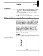
a. Purge the system with dry nitrogen for at least thirty minutes prior to
start-up to prevent the formation of deposits if reactive gas is to be
used.
b. In unpressurized piping, apply power to the controller and allow
approximately fifteen minutes for it to warm up and stabilize its
temperature.
c. Slowly apply gas pressure to the system.
d. Set the command for the desired pressure to assume normal operation.
3-2 Proportional Band and Integration Time Constant Adjustment
The Model 5866 Pressure Controller has proportional and integral control
action. The reset, or integral, control is combined with the proportional
control actions, commonly referred to as P.I. control. Both proportional
band and integration time are user adjustable. Refer to Figure 1-4 for P
and I adjustment potentiometer locations. The dynamic behavior of the
control system is influenced by flow range, pressure range, fluid type,
orifice size and system volume. Therefore, Model 5866 may have to be
adjusted in the field to achieve the best dynamic response.
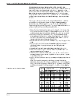
The factory settings are typically: proportional band minimum, 0.5%,
potentiometer fully counterclockwise (c.c.w.) and integration time
minimum, 0.05 seconds, potentiometer fully clockwise (c.w.). This
combination of adjustments usually results in stable control. For most
systems the dynamic response is adequate with the factory settings.
Improved response can be had by final tuning the P and I potentiometers
in the system by the user. The tuning of the P and I constants does not
affect the calibration of the instrument.
Definitions
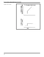
Both proportional and integral control actions are defined with respect to a
step response error signal. Refer to Figure 3-1.
Section
3
Figure 3-1. Error Signal Step
Response.
Содержание 5866
Страница 15: ...Brooks Instrument Model 5866 Pressure Controller 2 4 Figure 2 1 Customer Connections and Settings ...
Страница 20: ...3 3 Operation Figure 3 2 Proportional Control Figure 3 3 Integral Control ...
Страница 21: ...Brooks Instrument Model 5866 Pressure Controller 3 4 Figure 3 4 P I Control ...
Страница 23: ...Brooks Instrument Model 5866 Pressure Controller 4 2 ...
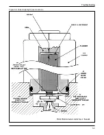
Страница 32: ...5 9 Troubleshooting Figure 5 3 Valve Adjusting Spacer Locations ...
Страница 34: ...5 11 Troubleshooting Figure 5 4 Valve Adjusting Spacer Locations Normally Open N O Valve ...
Страница 43: ...Brooks Instrument Model 5866 Pressure Controller 6 6 ...
Страница 45: ...Brooks Instrument Model 5866 Pressure Controller 7 2 Figure 7 1 Model 5866E Parts Drawing ...
Страница 47: ...Brooks Instrument Model 5866 Pressure Controller 7 4 Figure 7 2 Model 5866M Parts Drawing ...
Страница 48: ...7 5 Parts List Table 7 3 Model 5866M Parts List ...
Страница 49: ...Brooks Instrument Model 5866 Pressure Controller 7 6 ...
Страница 65: ......


