Bronkhorst®
Instruction Manual FLEXI-FLOW™ Compact
9.17.158A
22
FLOW-BUS
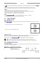
FLOW-BUS uses the ProPar protocol, where parameters are identified by a unique combination of a process number and a
parameter number:
[Pro]
Process number
[Par]
Parameter number
·
For more information about setting up a FLOW-BUS network with Bronkhorst® instruments, consult the FLOW-BUS
manual (see
).
·
For more detailed information on the ProPar protocol, consult the RS-232 manual (see
).
Modbus
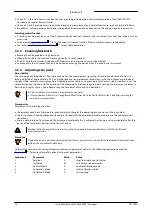
In the Modbus protocol, parameters are accessed by specifying their unique decimal register number or corresponding PDU
address (Protocol Data Unit). The PDU address is the hexadecimal translation of the register number minus 1, e.g. register
number 1 corresponds to PDU address 0x0000, register number 11 corresponds to PDU address 0x000A:
[address]
Hexadecimal PDU address
[register]
Decimal register number
Modbus address blocks are two bytes big. Larger data types use up to 8 subsequent address blocks, resulting in a
maximum variable length of 16 bytes. Values longer than the maximum length are truncated.
For more detailed information about setting up a Modbus network with Bronkhorst® instruments, consult the Modbus
manual (see
).
4.2.1
Measurement and control
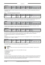
Measure
Type
Access
Range
FlowDDE
FLOW-BUS
Modbus
Unsigned int
R
0…41942
8
1/0
0x0020/33
This parameter indicates the flow metered by the instrument. The value of 32000 corresponds to 100%, the maximum
measured value output is 131.07%, which translates to 41942.
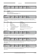
Setpoint
Type
Access
Range
FlowDDE
FLOW-BUS
Modbus
Unsigned int
RW
0…32767
9
1/1
0x0021/34
This parameter is used to set the required flow rate for the controller. Within the setpoint range, value 32000 corresponds to
100%
To convert
Measure
and
Setpoint
to actual mass or volume flows, use parameters
Capacity
and
Capacity Unit
(see
)
Control Function
Type
Access
Range
FlowDDE
FLOW-BUS
Modbus
Unsigned char
RW
0, 1, 2
147
115/10
0x0E6A/3691
·
This parameter determines whether the instrument works as a flow controller or a pressure controller.
·
Use the setpoint on the associated communication channel to control the flow or pressure.
·
The selected function is effective immediately.
·
The instrument remembers the selected value on restart (persistent setting).
Available functions:
Value
Description
0
Flow (channel 1)
1
Upstream pressure (channel 2)
2
Downstream pressure (channel 3)
9
9
9
28


