C_001 rev.03
10
BROLLO SIET S.r.l. – Via Mazzini, 24 – 31031 CAERANO SAN MARCO (TV) – tel +39.(0)423.657.550 – Fax +39.(0)423.650.337
http//:www.brollosiet.com E-mail: [email protected]
4.
INSTALLATION
4.1.
STANDARD
SUPPLY
•
LED display (corresponding to the order)
•
Supply cable 230 V +/- 10% for the required kind of product
•
Assembly instructions.
4.2.
OPTIONAL SUPPLY
•
Accessories according to the order.
4.3.
ASSEMBLY INSTRUCTIONS
1.
According to the ordered model, place the display on a solid base or fix carefully the brackets on
the holes on the box.
2.
Firmly fix the brackets, if present, in case of anchorage to walls or ceilings using appropriate
hanging systems.
3.
Be sure that the ve ventilation holes, if present, are not obstructed and that walls or other things do
not stop the air circulation.
4.4. W
IRING
–
DC INPUT VERSION
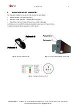
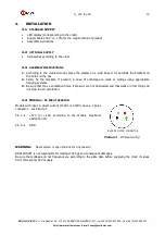
Models with input in direct current (12Vdc or 24Vdc) have a 4 poles
connector – see Picture 1.
Pin 1
+12V (or +24V, according to the model), maximum
absorption 2A
Pin 4
GND
Picture 1
– DC input wiring
WARNING:
Never pierce or open the box for any reason!
BROLLO SIET is not responsible for improper fixings and consequent damages.
Be sure that voltage and net frequency are according to the plate data before supplying the clock: if values
don’t correspond, don’t supply.
BACK OF FLYING CONNECTOR


