


DANGER
Disconnect the power cord from all power sources to completely remove power from the device.
DANGER
Use safe lifting practices when moving the product.
DANGER
Make sure the rack housing the device is adequately secured to prevent it from becoming unstable or falling over.
DANGER
A completely empty chassis weighs approximately 24.49 kg (54 lb) and requires a hydraulic or assisted lift to install it.
Chassis replacement task guide
Following are the basic tasks for removing and replacing the chassis with its backplane.
NOTE
The device must be removed from the fabric and powered off to perform these tasks. Contact your support provider if you have
any questions about whether the chassis requires replacement.
1.
Recording critical device and SAN information
2.
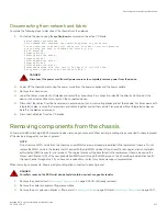
Disconnecting from network and fabric
3.
Removing components from the chassis
4.
Installing the replacement chassis
5.
Installing components into the chassis
6.
7.
Reconnecting system to the network and fabric
on page 220
8.
Verifying correct operation of system
on page 221
9.
Verifying correct operation of system
on page 221
Chassis fault indicators
Verify that replacement of the chassis is necessary. If error messages and LED operation indicates faulty components, ensure that the
components are firmly seated. Contact your support provider with any questions about whether the chassis should be replaced.
Any of the following events might indicate the need to replace the chassis:
•
Visible mechanical damage to the chassis, including damage to sheet metal or card guides that prevents correct installation of a
blade.
•
Bent or damaged connectors on the backplane (the surface inside the chassis to which the blades connect).
•
One or more components (such as a power supply, blower assembly, port blade, control processor blade, core switch blade, or
WWN card) do not function properly even after the component was replaced.
•
Intermittent FAULTY codes for blades. Reseat the blade and visually inspect the ejector stiffening rails for possible wear or
damage. It is important that the blade ejector handles not slip out during blade installation. If this happens, it is usually due to
excessive wear or damage to the ejector stiffening rails.
Chassis replacement task guide
Brocade X6-4 Director Hardware Installation Guide
212
53-1004106-07
Содержание X6-4
Страница 12: ...Brocade X6 4 Director Hardware Installation Guide 12 53 1004106 07...
Страница 20: ...Brocade X6 4 Director Hardware Installation Guide 20 53 1004106 07...
Страница 28: ...Brocade X6 4 Director Hardware Installation Guide 28 53 1004106 07...
Страница 64: ...Brocade X6 4 Director Hardware Installation Guide 64 53 1004106 07...
Страница 86: ...Brocade X6 4 Director Hardware Installation Guide 86 53 1004106 07...
Страница 102: ...Brocade X6 4 Director Hardware Installation Guide 102 53 1004106 07...
Страница 130: ...Brocade X6 4 Director Hardware Installation Guide 130 53 1004106 07...
Страница 140: ...Brocade X6 4 Director Hardware Installation Guide 140 53 1004106 07...
Страница 166: ...Brocade X6 4 Director Hardware Installation Guide 166 53 1004106 07...
Страница 196: ...Brocade X6 4 Director Hardware Installation Guide 196 53 1004106 07...
Страница 200: ...Brocade X6 4 Director Hardware Installation Guide 200 53 1004106 07...
Страница 204: ...Brocade X6 4 Director Hardware Installation Guide 204 53 1004106 07...
Страница 210: ...Brocade X6 4 Director Hardware Installation Guide 210 53 1004106 07...
Страница 224: ...Brocade X6 4 Director Hardware Installation Guide 224 53 1004106 07...
Страница 238: ...Brocade X6 4 Director Hardware Installation Guide 238 53 1004106 07...