


29
Section D – Electrical Components
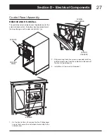
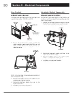
CONTROL BOARD
HARNESS
INTERLOCK
SWITCH
WIRE
KEY SWITCH
WIRES
Lifting the cover and noting their locations, fi rmly
3.
but gently disconnect the control board harness, the
wire at the interlock switch, and the key switch wires.
Remove the rear cover. NOTE: Illustration does not
show control board insulator.
SCREWS
Remove four Phillips head screws and the power
4.
supply board from the rear cover.
Installation is the reverse of removal.
5.
Control Board
REMOVE AND RE-INSTALL
The control board is used to electronically connect the
compactor’s electronic components.
CONTROL
BOARD
CONTROL
PANEL
SCREWS
DISPLAY
PANEL
Remove the control panel assembly (see Control
1.
Panel Assembly, Remove and Re-install). Remove
rear cover from the display module assembly (see
Display Module Assembly, Remove and Re-install).
SCREWS
WIRE
CONNECTOR
Remove the wire harnesses from control board (Note
2.
wire locations).
NOTE: In this illustration, the key switch and control
board insulator have been removed for clarity.
Remove six Phillips head screws, the printed circuit
3.
board, and the insulator from the display module
frame.
Installation is the reverse of removal.
4.
Содержание Elite 15XEBL
Страница 44: ......


