background image

Page 2

MODELS 744L • 744RL • 744RNL

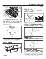
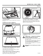
The ducting from this fan to the outside of the building has a strong 
effect on the air flow, noise and energy use of the fan. Use the 
shortest, straightest duct routing possible for best performance, 
and avoid installing the fan with smaller ducts than recommended. 
Insulation around the ducts can reduce energy loss and inhibit 
mold growth. Fans installed with existing ducts may not achieve 
their rated airflow.
Plan to supply the unit with proper line voltage and appropriate 
power cable.

INSTALLATION

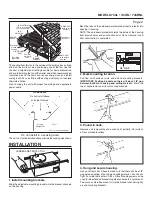
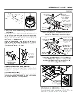
2. Mark mounting location.

Position unit between joists and extend mounting brackets.  

IMPORTANT: Position brackets so there will be an 1/8” gap 
between bottom of housing and ceiling material.

  Mark the 

top of keyhole slot on all four mounting brackets.

The unit must not be installed above or inside the cooking area shown.

Do not install in a cooking area.

COOKING AREA

Do not install above

or inside this area 

Cooking

Equipment

Floor

45

45

1/8" GAP

1. Install mounting brackets.

Slide the adjustable mounting brackets into the bracket channels 
on the housing.

CARDBOARD PROTECTOR

*Purchase

separately.

INSULATION* 

(Place around and 

over Fan Housing.)

ROOF CAP*

(with built-in

damper)

FAN

HOUSING

POWER

CABLE*

4-IN. ROUND

DUCT*

4-IN.

ROUND

ELBOWS*

Seal gaps

around

Housing.

Seal duct

joints with

tape.

OR

Keep duct

runs short.

   WALL CAP* 

(with built-in

damper)

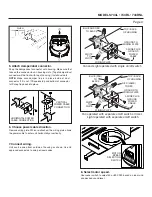
Bend the tabs on the cardboard protector and insert protector into 
opening in housing.
NOTE: The cardboard protector shields the inside of the housing 
from drywall spray and construction dust. Do not remove it until 
after construction is completed.

3. Pound in nails.

Remove unit temporarily, and pound nails partially into joists at 
all four marked locations.

4. Hang and secure housing.

Hang unit from nails. Check to make sure that there will be a 1/8” 
gap between bottom of housing and ceiling material.  Pound nails 
tight.  For wide joist centers:  A #8 x 3/8 self-tapping screw can be 
used to join extended brackets together and create a rigid mount.  
To ensure a noise-free mount, crimp the bracket channels tightly 
around mounting brackets.

Содержание 744L

Страница 1: ...hower it must be marked as appropriate for the application and be connected to a GFCI Ground Fault Circuit Interrupter protected branch circuit 13 Do not install in a ceiling thermally insulated to a value greater than R60 14 This unit must be grounded CAUTION 1 For general ventilating use only Do not use to exhaust hazardous or explosive materials and vapors 2 To avoid motor bearing damage and no...

Страница 2: ...Equipment Floor 45 45 1 8 GAP 1 Install mounting brackets Slide the adjustable mounting brackets into the bracket channels on the housing CARDBOARD PROTECTOR Purchase separately INSULATION Place around and over Fan Housing ROOF CAP with built in damper FAN HOUSING POWER CABLE 4 IN ROUND DUCT 4 IN ROUND ELBOWS Seal gaps around Housing Seal duct joints with tape OR Keep duct runs short WALL CAP with...

Страница 3: ...ed connectors to wire per local codes Fan and Light operated with single on off switch RED LAMP TO RED WIRING PLATE WHITE TO WHITE BLUE AND RED TO BLACK TOP BACK OF HOUSING 2 WIRE PLUS GROUND POWER CABLE GROUND TO WIRING PLATE FLUSH 5 Attach damper duct connector Snap the damper duct connector onto housing Make sure that tabs on the connector lock in housing slots Top of damper duct connector will...

Страница 4: ... other lamp types Do not install a lamp indentified for use only in enclosed luminaries CLEARANCE HOLE 10 Install optional trim ring to trim ring baffle Trim rings not included with Model 744L Remove the cardboard protector from inside the housing collar Place trim ring over trim ring baffle Place fingers directly above and below tab as shown with arrows and squeeze to snap tab securely to trim ri...

Страница 5: ... ducha debe estar marcada como apropiada para esta aplicación y conectarse a un GFCI interruptor accionado por pérdida de conexión a tierra en un circuito de derivación protegido 13 No se debe instalar en un techo que tenga un valor de aislamiento térmico superior a R60 14 Esta unidad debe estar conectada a tierra PRECAUCIÓN 1 Soloparausarsecomomediodeventilacióngeneral Nodebeusarse para la extrac...

Страница 6: ...DE 1 8 pulg 3 mm 1 Instale los soportes de montaje Deslice los soportes de montaje ajustables en los canales del soporte de la cubierta PROTECTOR DE CARTÓN TAPA DE TECHO con regulador de tiro integrado TAPA DE PARED con regulador de tiro integrado CODOS REDONDOS DE 10 CM 4 PULG CONDUCTO REDONDO DE 10 CM 4 PULG CUBIERTA DEL VENTILADOR Selle las separaciones alrededor de la cubierta Selle con cinta ...

Страница 7: ... y lámpara controlados mediante un interruptor único de encendido apagado ROJO LÁMPARA A ROJO PLACA DE CABLEADO BLANCO A BLANCO AZUL Y ROJO A NEGRO PARTE SUPERIOR PARTE POSTERIOR DE LA CUBIERTA CABLE ELÉCTRICO DE DOS HILOS Y CONEXIÓN A TIERRA TIERRA A PLACA DE CABLEADO AL RAS 5 Acople el conectador del regulador de tiro conducto Conecte a presión el conector del regulador de tiro conducto en la cu...

Страница 8: ...a resorte en los agujeros que están en el soporte de la lámpara Centre el anillo deflector en la abertura del cielo raso 10 Instale el anillo opcional al anillo deflector No se incluyen anillos con el Modelo 744L Quite el protector de cartón del interior del collar de la cubierta Coloque el anillo sobre el anillo deflector Coloque los dedos directamente arriba y abajo de la lengüeta como se muestr...

Отзывы: