Self Regulating Heating Cable
© BriskHeat
®
Corporation. All rights reserved.
23
Maximum Circuit Length in Feet Vs. Circuit Breaker Size
Heat Cable
Type
Circuit
Breaker
Size
Start-up Temperature
50°F
(10°C)
32°F
(0°C)
-4°F
(-20°C)
-40°F
(-40°C)
SLHCBL5120
10 amp
120
110
105
90
15 amp
180
175
158
143
20 amp
240
215
190
180
30 amp
259
245
240
225
40 amp
266
255
250
240
SLHCBL5240
10 amp
240
220
210
180
15 amp
360
350
315
285
20 amp
479
430
380
360
30 amp
518
490
480
450
40 amp
531
510
500
480
SLHCBL10120
10 amp
73
69
65
58
15 amp
118
110
98
88
20 amp
148
140
130
118
30 amp
220
200
182
175
40 amp
255
240
220
230
SLHCBL10240
10 amp
146
138
130
116
15 amp
236
220
195
175
20 amp
295
280
260
235
30 amp
440
400
364
350
40 amp
510
480
440
460
SLHCBL15120
10 amp
50
47
42
40
15 amp
75
65
63
60
20 amp
100
90
83
80
30 amp
143
135
125
120
40 amp
190
175
168
160
SLHCBL15240
10 amp
100
93
83
80
15 amp
150
130
125
120
20 amp
200
180
165
160
30 amp
285
270
250
240
40 amp
380
350
335
320
SLHCBL20120
10 amp
39
33
34
32
15 amp
58
55
50
48
20 amp
75
71
68
63
30 amp
115
105
100
95
40 amp
153
143
133
125
10 amp
77
70
67
63
15 amp
115
110
100
95
20 amp
150
142
135
125
30 amp
230
210
200
190
40 amp
306
286
265
250
SLHCBL20240
Voltage Adjustment Factors
Product Type
208 VAC
277 VAC
SLHCBL5240
0.87
1.07
SLHCBL10240
0.88
1.08
SLHCBL15240
0.88
1.08
SLHCBL20240
0.86
1.07
Watt/ft Output Adjustment Factor
Product Type
208 VAC
277 VAC
SLHCBL5240
0.99
1.08
SLHCBL10240
0.99
1.06
SLHCBL15240
0.98
1.06
SLHCBL20240
1.00
1.08
Max Circuit Length Adjustment Factor
SLHCBL
Figure 17
Heat Output (Watts per Foot)
Po
w
er Outp
ut,
W
/ft
21
18
15
12
9
6
3
0
A
B
C
D
D = 20 W/FT
C = 15 W/FT
B = 10 W/FT
A = 5 W/FT
32(0)
68(20)
104(40)
140(60) 176(80)
212(100) 248(120)
Pipe Temperature, °F(°C)
Self Regulating Heating Cable
© BriskHeat
®
Corporation. All rights reserved.
24
Ground Fault Protection
Ground fault circuit breakers are required on all heater constructions per the National Electric Code. Typically, 30ma trip devices are
required due to the capacitive leakage of the heating cable construction.
Waterproofing
Moisture penetration of the electrical system is the single largest source of problems in a heating cable system installation. Therefore,
particular care must be given to the proper sealing of all electrical connections and splices. Heating cable sealing kits will provide a
proper seal for the heating cable itself, when used per kit instructions. All other electrical connections (heater to power wiring,
thermostat connections, panel and breaker connections, etc.) should be sealed or moisture proofed in some fashion. Either mastic
shrink tube or an aerosol electrical insulative sealant should be used on all connections to reduce any moisture penetration. The
sealant will also reduce the potential for corrosion on exposed metal parts.
TESTING
Recommendations
Electrical tests are recommended at specific points in the receipt and installation of the heating cable. This periodical testing is
designed to prevent the expenditure of wasted labor in the event of damage to the product. Installation costs of the cable and thermal
insulation are much greater that the heating cable. Quick identification of any heating cable damage is the most economic approach to
an installation. An insulation resistance test is recommended at the following point of the installation process:
UPON RECEIPT of the heating cable
BEFORE thermal INSULATION installation
IMMEDIATELY AFTER thermal insulation installation
As part of a PERIODIC MAINTENANCE program
Procedure
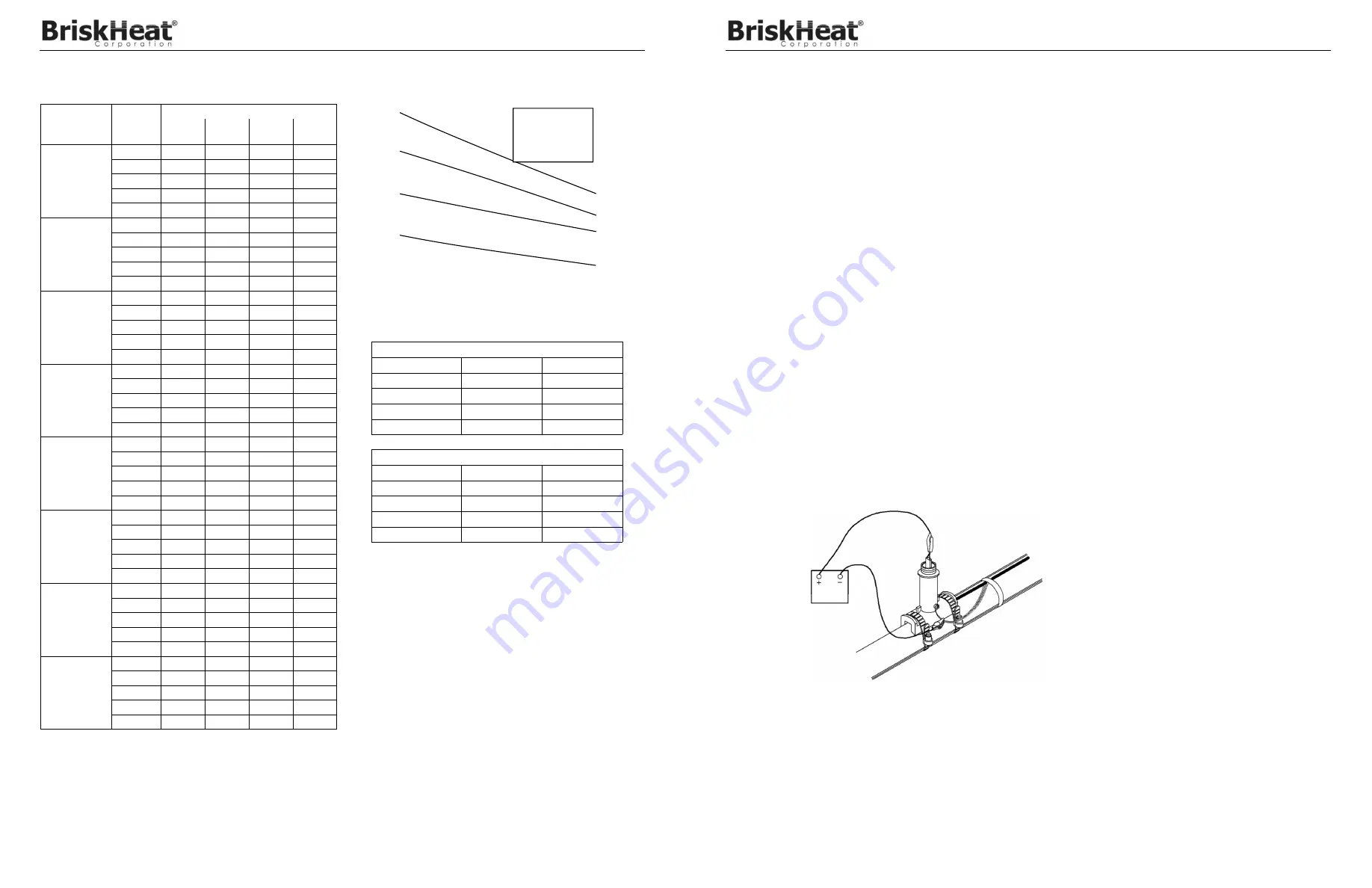
The insulation resistance test is used to check for damage to extruded jackets. Connections for the megger are made as shown in
Figures 18 & 19
.
Note: Test should use at least a 500 VDC megger. Do not use a megger with an excess of 2500 VDC. Minimum acceptable readings
should be 20 megohms per circuit, regardless of length.
Figure 18
500 VDC
MEGGER
FOR HEATING CABLES WITH BRAID
Test from heating cable bus to braid


