background image

C-8

Revision 1.1

04/2022

M0261 EN

C-8

MOUNTING & WIRING

MOUNTING TO THE WALL 5 - 8 PUMP SYSTEM

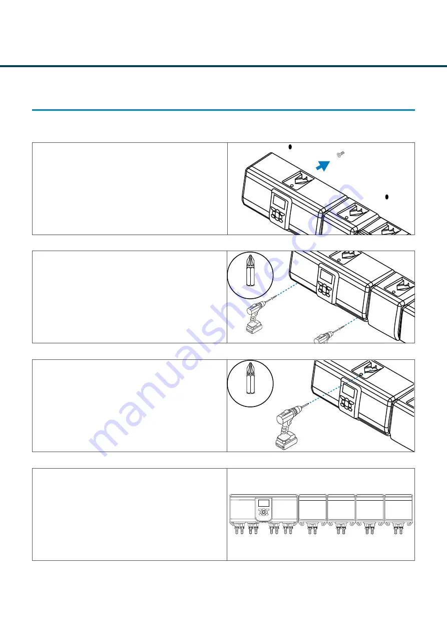
STEP 13

Place the unit back over the original screw mount.

STEP 14

Align the unit using the spirit level located on the bottom 

of the unit with the wall plugs. Take the M5 pozi screws 

provided  and screw into place. 

PLEASE NOTE - 

Do not over tighten as this will 

damage the unit.

STEP 15

Finally, once you are happy with the placement. Screw 

the top screw in the last part to make it a secure fit to the 

wall.

STEP 16

Your unit is now mounted to the wall and ready to wire in.

M5 Pozi

M5 Pozi

Содержание Nexus Laundry System

Страница 1: ...Revision 1 1 02 2021 M0261 EN Nexus Laundry System Instruction Manual Installation and setup Brightwell co uk...

Страница 2: ...ARD B 6 LAYOUT FORMULA SELECT SCREEN B 7 UNIT VARIATIONS B 8 MOUNTING WIRING MOUNTING TO THE WALL 4 PUMP SYSTEM C 1 MOUNTING TO THE WALL 5 8 PUMP SYSTEM C 5 WIRING GUIDE POWER C 9 WIRING GUIDE POWER C...

Страница 3: ...D FLOW RATE AND CALIBRATION D 14 PUMP STOP MODE D 15 CHANGE UNIT MODE D 16 CHANGE UNIT OF MEASUREMENT D 18 CREATING A WASHPROGRAM CREATING A PROGRAM STANDARD MODE E 1 CREATING A PROGRAM LEVELS MODE E...

Страница 4: ...GS RF SETTINGS F 20 SETTINGS SET BLUETOOTH POWER F 24 SETTINGS CYCLE COUNTERS F 26 FORMULA SELECT FORMULA SELECT PUMP STOP G 2 FORMULA SELECT PRIME PUMP G 3 FORMULA SELECT SELECT PROGRAM G 4 FORMULA S...

Страница 5: ...GENERAL INFORMATION A Section...

Страница 6: ...supply sources Do not power the unit outside of the values stated on the rating label Do not use damaged or frayed cables Do not dismantle or modify this equipment Do not mount the unit to unstable ir...

Страница 7: ...facturer regarding safety advice Follow the instructions carefully to avoid accidents Do not open the enclosure without isolating the signal and supply sources Ensure that these sources have been isol...

Страница 8: ...efore operating at the programmed speed for the programmed run time or chemical dosage The pump will not operate again until the unit has reset The unit can be selected to reset after the operation of...

Страница 9: ...TECHNICAL INFORMATION B Section...

Страница 10: ...uding any packaging This unit is ONLY to be installed by a suitably qualified person complying with local regulations NEXUS 4 Pump to 8 Pump system Based on order Wall mounting pack Wall plug x 3 M5 s...

Страница 11: ...8 3A 240V CURRENT 1 Pump 75W 5 Pump 103W 6 Pump 131W 7 Pump 159W 8 Pump 187W TRIGGER SIGNALS 12 240V AC or DC MOTOR Flush Valve 24V DC 1 25A 10W max Buzzer Lamp 24V DC 500Ma 10W max PUMP Membrane Pum...

Страница 12: ...B 3 Revision 1 1 04 2022 M0261 EN B 3 technical information ADDITIONAL PUMP MODULE ENCLOSURE MEMBRANE PUMP ENCLOSURE DISPLAY KEYPAD MAIN DISPLAY KEYPAD FORMULA SELECT ENCLOSURE DISPLAY KEYPAD...

Страница 13: ...tion LAYOUT MAIN UNIT SCREEN L4 PUMP MESSAGE FAULT MESSAGE If there are any errors on the unit the message will show here NUMBER OF PUMPS Displays the number of connected pumps to the unit ANY RUNNING...

Страница 14: ...5 technical information 3 MOTOR CONNECTORS 1 PAIR BUTTON 2 ETHERNET LAYOUT MAIN PCB 4 ADD ON PUMP 6 MULTIDOSE AND OR FLOW SENSOR MODULE 7 MANIFOLD SAFETY STOP SWITCHES 5 IOM 9 24 VOLT POWER 8 FLOAT S...

Страница 15: ...cal information 12 34 56 78 9 LAYOUT IO BOARD 3 COMMON NEUTRAL 1 MAINS POWER IN 2 MAINS OUT 4 TRIGGER INPUT 5 ISOLATED GROUND 8 24 VOLT OUT 6 CONNECTION TO MDU PREVIOUS IOM 7 OUTPUT TO IOM 9 FORMULA S...

Страница 16: ...B 7 Revision 1 1 04 2022 M0261 EN B 7 technical information LAYOUT FORMULA SELECT SCREEN PROGRAM NAME PROGRAM NUMBER PROGRAM RUN COUNT PG01 000000 Program Name...

Страница 17: ...B 8 Revision 1 1 04 2022 M0261 EN B 8 technical information UNIT VARIATIONS 4 PUMP VARIANT 5 PUMP VARIANT 6 PUMP VARIANT 7 PUMP VARIANT...

Страница 18: ...B 9 Revision 1 1 04 2022 M0261 EN B 9 technical information 8 PUMP VARIANT UNIT VARIATIONS...

Страница 19: ...MOUNTING WIRING C Section...

Страница 20: ...following boundaries MOUNTING TO THE WALL 4 PUMP SYSTEM STEP 1 Place the unit against the wall where you would like to install PLEASE NOTE The unit should not be more than 2 metres from the chemical...

Страница 21: ...the pack and use a screwdriver not provided to screw into the wall PLEASE NOTE There must be at least 50 mm left outside of the wall for the unit to mount correctly as illustrated STEP 7 Take the Nexu...

Страница 22: ...ry to get them as central as possible MOUNTING TO THE WALL 4 PUMP SYSTEM STEP 10 Remove the unit from the wall to reveal the drill marks STEP 11 Drill two holes using the same 6mm drill bit as before...

Страница 23: ...irit level located on the bottom of the unit with the wall plugs Take the M5 pozi screws provided and screw into place PLEASE NOTE Do not over tighten as this will damage the unit STEP 15 Finally once...

Страница 24: ...the following boundaries STEP 3 Once you have confirmed the location for the unit take a pencil or similar marker and place a dot in the top mount ing hole for the main unit and each of the additiona...

Страница 25: ...led hole If re quired use a hammer or mallet not provided to drive flush STEP 6 Take the M5 screw from the pack and use a screwdriver not provided to screw into the wall PLEASE NOTE There must be at l...

Страница 26: ...ting holes for the main unit and all the additional pumps Try to get them as central as possible STEP 10 Remove the unit from the wall to reveal the drill marks STEP 11 Drill the holes using the same...

Страница 27: ...it level located on the bottom of the unit with the wall plugs Take the M5 pozi screws provided and screw into place PLEASE NOTE Do not over tighten as this will damage the unit STEP 15 Finally once y...

Страница 28: ...STEP 2 Pull the front cover up PLEASE NOTE The screen is attached with wires take care not to damage when detaching the cover STEP 3 Use the hooks at the top of the enclosure to hold the cover in plac...

Страница 29: ...1 EN C 10 mounting wiring STEP 5 Remove the 3 way green connector on the power supply as illustrated Place the 3 core mains wire rated 110 240 AC into the slot located on the IO board WIRING GUIDE POW...

Страница 30: ...the input put the dip switch in the BOTTOM position For ISOLATED NEUTRAL place it in the TOP position WIRING GUIDE TRIGGER SIGNALS STEP 1 The TRIGGER SIGNALS are located inside the unit on the right...

Страница 31: ...rail Make sure to wire the correct trigger to the above dip switch The trigger signals can be either 24 volt DC or 240 volt AC WIRING GUIDE TRIGGER SIGNALS TRIGGER 1 8 M3 POZI STEP 4 Now that you have...

Страница 32: ...this input will denote the program number PLEASE NOTE This relies on the MULTIPLIER set in section INSERT SECTION NUMBER E G With a multiplier of 1 1 second Program 1 2 seconds Program 2 AFS 9 M3 POZ...

Страница 33: ...3 WIRING GUIDE AUTO FORMULA SELECT BINARY PROGRAM NO INPUT 1 INPUT 2 INPUT 3 INPUT 4 INPUT 5 PROGRAM 1 1 0 0 0 0 PROGRAM 2 0 1 0 0 0 PROGRAM 3 1 1 0 0 0 PROGRAM 4 0 0 1 0 0 PROGRAM 5 1 0 1 0 0 PROGRAM...

Страница 34: ...24 volt live and neutral STEP 1 The manifold connectors are located inside the main unit in the position illustrated here WIRING GUIDE MANIFOLD PROGRAM NO INPUT 1 INPUT 2 INPUT 3 INPUT 4 INPUT 5 PROG...

Страница 35: ...ty switch STEP 1 The manifold connectors are located inside the main unit in the position illustrated here Neutral 24 Volt DC Safety Switch Neutral Safety Switch Input STEP 2 The wiring for the connec...

Страница 36: ...PROGRAMMING THE UNIT D Section...

Страница 37: ...1 Revision 1 1 04 2022 M0261 EN D 1 Programming the Unit PROGRAM BUTTON SKIP BUTTON PRIME BUTTON TEST BUTTON ARROW NAVIGATION PUMP STOP STANDBY MODE MOVE FORWARD AND BACK MOVE UP AND DOWN CHANGE SETTI...

Страница 38: ...The next screen will ask you to set a password Use the UP and DOWN arrow keys to select YES or NO Use the RIGHT arrow to advance to the next screen STEP 4 If you select YES you will be asked to set a...

Страница 39: ...Unit INITIAL SETUP STEP 5 The final screen will allow you to switch the unit of mea surement from TIME to ML FL OZ or GRAMS Use the UP and DOWN arrow to change selection RIGHT arrow to confirm Change...

Страница 40: ...trated STEP 2 Take the zip ties provided and attach to the top of the pipe to create a tight seal STEP 3 It is recommended to use snips to remove any excess left on the tie as illustrated STEP 4 The l...

Страница 41: ...e chemical ready for delivery To do this press the PRIME button on the main keypad STEP 7 Select the pump you wish to prime using the UP and DOWN arrows Then PRESS and HOLD the MIDDLE button to PRIME...

Страница 42: ...Cycle screen STEP 2 Input information is displayed on this screen When a signal is received to the input it will change from a 0 to a 1 Press the UP button to move to Total Washcycles STEP 4 The firm...

Страница 43: ...e prime pump screen Note If a manifold has been assigned the pump and flush will prime together STEP 2 From here you can select the pump that you wish to prime with the UP or DOWN arrow STEP 3 When th...

Страница 44: ...rom the Pump Prime menu press the TEST button to select to the Flush Valve menu STEP 3 In the Flush Valve menu use the LEFT and RIGHT arrow to select the valve you wish to prime L4 Pumps Brightwell Pr...

Страница 45: ...enu press the TEST button to take you to the Flush Valve menu STEP 7 In the Flush Valve menu use the UP or DOWN arrow to select the Flush Valve and Pump menu STEP 8 From the Flush and Pump Prime menu...

Страница 46: ...1 1 04 2022 M0261 EN D 10 Programming the Unit FLUSH VALVE PUMP PRIME SCREEN STEP 9 When the correct valve and pump is selected press and hold the REPORTS button on the keypad to prime PRIME FLUSH VAL...

Страница 47: ...o navigate to the Flush Manifold Settings STEP 3 On the Flush Valve Settings screen select YES using the UP or DOWN arrow STEP 4 On the next screen use the UP and DOWN arrows to change which flush val...

Страница 48: ...ween BEFORE and AFTER to AFTER ONLY using the UP and DOWN arrow Press the RIGHT arrow to advance and save each setting STEP 6 Finally you can set the Flush Time using the UP and DOWN arrow to change t...

Страница 49: ...ceed forward STEP 2 Press the RIGHT key to advance to the Operational Settings menu STEP 3 Press the RIGHT key to advance past the Flush Valve Settings menu STEP 4 On the next screen change the select...

Страница 50: ...wish to calibrate the pump for using the PRIME but ton To begin the calibration press the TEST button Adjust Speed Confirm Advance PUMP SPEED 100 Enter Calibration Menu PUMP SPEED 100 Adjust Calibrati...

Страница 51: ...utton located on the main keypad STEP 2 To deactivate a pump use the RIGHT and LEFT arrow to select the correct pump Then press UP to move it to the OFF section Once complete press the PUMP STOP butto...

Страница 52: ...on the Operational Settings menu Use the UP or DOWN arrows to navigate to the SYSTEM SETTINGS menu STEP 3 Press the RIGHT arrow to advance into the System Settings menu STEP 4 The first selection will...

Страница 53: ...g the Unit CHANGE UNIT MODE STEP 5 The default for the unit will be Standard Mode Use the UP or DOWN arrow to change to the mode you want to use Press the RIGHT arrow to advance and save each setting...

Страница 54: ...perational Settings menu Use the UP or DOWN arrows to navigate to the SYSTEM SETTINGS menu STEP 3 Press the RIGHT arrow to advance into the System Settings menu STEP 4 Use the UP and DOWN arrow to cha...

Страница 55: ...STEP 5 Use the UP and DOWN arrow to select the unit of measurement you wish to use You can choose between TIME MS ML GRAMS and FL OZ Once you have the unit you wish to use highlighted Press the RIGHT...

Страница 56: ...CREATING A WASHPROGRAM E Section...

Страница 57: ...ess the RIGHT arrow and enter the pass code to proceed forward STEP 2 Press the RIGHT arrow to advance into the Operational Settings menu STEP 3 Press the RIGHT arrow to advance past the Pump Speed an...

Страница 58: ...RIGHT to advance and save the setting STEP 7 Once you have chosen the program you will be asked to pick the input you wish to program using the UP and DOWN keys Press the RIGHT to advance and save th...

Страница 59: ...C number Press the RIGHT and LEFT arrow to move between them Press the RIGHT arrow to advance and save each setting STEP 11 This screen will allow you to adjust the run time total dosage for the enabl...

Страница 60: ...Once you are happy you can press the SKIP button to jump forward STEP 15 The default for the Program Reset will be the last pump connected to the unit Alternatively you can change this to a particula...

Страница 61: ...TANDARD MODE STEP 17 After the Reset Delay Time has been set you can be adjust which program blank program the unit will reset to Change this with the UP and DOWN arrows Press the RIGHT arrow to advan...

Страница 62: ...ck the RIGHT arrow and enter the pass code to proceed forward STEP 2 Press the RIGHT arrow to advance into the operational settings menu STEP 3 Press the RIGHT arrow to advance past the pump speed and...

Страница 63: ...ance and save the setting STEP 7 Once you have selected the program you can set the Delay Time for level 1 Use the UP and DOWN arrow to change the setting Press the RIGHT arrow to advance and save the...

Страница 64: ...been setup you can select to move to a new program Alternatively SKIP will move onto the Reset Settings STEP 11 The default for the reset will be the load pump connected to the unit This will incremen...

Страница 65: ...ignal with the UP and DOWN arrow Press the RIGHT arrow to advance and save the setting Examples Multiplier x 1 1 second signal Program 1 Multiplier x 2 2 second signal Program 1 etc STEP 3 If BINARY m...

Страница 66: ...SETTINGS F Section...

Страница 67: ...P 4 Use the UP and DOWN arrow to select the set language menu ENTER PASSCODE Advance STEP 2 You will be placed on the Operational Settings menu Use the UP or DOWN arrows to navigate to the SYSTEM SETT...

Страница 68: ...TTINGS CHANGE LANGUAGE STEP 5 From here you can change the language of the unit using the UP and DOWN arrows Once you have found the correct language press the RIGHT arrow to save the setting and conf...

Страница 69: ...row to select the set Date and Time menu Use the RIGHT arrow to enter the menu ENTER PASSCODE Advance STEP 2 You will be placed on the Operational Settings menu Use the UP or DOWN arrows to navigate t...

Страница 70: ...n change the Date and Time of the unit Use the UP and DOWN arrows to change the highlighted number LEFT and RIGHT to move between the digits Once you have set the correct Time and Date press the RIGHT...

Страница 71: ...and DOWN arrow to select the Set Access Code menu Use the RIGHT arrow to advance ENTER PASSCODE Advance STEP 2 You will be placed on the Operational Settings menu Use the UP or DOWN arrows to navigate...

Страница 72: ...re you can change the Access Code of the unit Use the UP and DOWN arrows to change the highlighted number LEFT and RIGHT to move between the digits Once you have set the desired Access Code press the...

Страница 73: ...row to select the Set Flow Switch Acceptance Time menu Use the RIGHT arrow to advance ENTER PASSCODE Advance STEP 2 You will be placed on the Operational Settings menu Use the UP or DOWN arrows to nav...

Страница 74: ...he Flow Switch Acceptance Time of the unit Use the UP and DOWN arrows to change the highlighted number LEFT and RIGHT to move between the digits Once you have set the desired Flow Switch Acceptance pr...

Страница 75: ...tional Settings menu Use the UP or DOWN arrows to navigate to the SYSTEM SETTINGS menu STEP 3 Press the RIGHT arrow to advance into the System Settings STEP 1 Please note This is a multimachine functi...

Страница 76: ...DE STEP 5 In the PRIME TO menu you can select the port you wish the multi machine to prime to Use the UP and DOWN arrow to select either the CALIBRATION PORT or outlets PORTS 1 6 Press the RIGHT arrow...

Страница 77: ...the Prime Mode Pump Stop Mode View Mode settings menu Use the RIGHT arrow to advance ENTER PASSCODE Advance STEP 2 You will be placed on the Operational Settings menu Use the UP or DOWN arrows to nav...

Страница 78: ...rrow to advance and save setting STEP 7 To change the Pump Stop Mode settings use the UP and DOWN arrows to move the following selection Use RIGHT to advance into the Pump Stop menu STEP 8 Use the UP...

Страница 79: ...View Mode settings use the UP and DOWN arrows to move the following selection Press the RIGHT arrow to advance into the View Mode menu STEP 10 Use the UP and DOWN to enable or disable The RIGHT arrow...

Страница 80: ...ional Settings menu Use the UP or DOWN arrows to navigate to the SYSTEM SETTINGS menu STEP 3 Press the RIGHT arrow to advance into the system settings STEP 4 Use the UP and DOWN arrows to select the N...

Страница 81: ...he number selected move between them using the LEFT and RIGHT arrows STEP 2 Use the UP and DOWN arrows to enable or disable Press the RIGHT arrow to confirm and save setting STEP 3 On the following sc...

Страница 82: ...e selection between the options Press the RIGHT arrow to confirm and save selection STEP 6 If you have selected Manual you will be asked to enter the preferred DNS sever address The LEFT and RIGHT arr...

Страница 83: ...and DOWN to move to the WIFI Settings menu Press the RIGHT arrow to confirm and move into the menu STEP 3 Press the UP and DOWN arrow to Enable or Disable the WIFI Press the RIGHT arrow to confirm and...

Страница 84: ...When you have entered the full password continue to press the RIGHT arrow to confirm selection and save STEP 6 The unit will then attempt to connect to the network If it has been successful it will c...

Страница 85: ...u STEP 3 Use the UP and DOWN arrow to change the MQTT Broker address RIGHT and LEFT to navigate RIGHT to confirm STEP 1 Use the UP and DOWN arrows until select Network Settings menu is highlighted Pre...

Страница 86: ...rational Settings menu Use the UP or DOWN arrows to navigate to the SYSTEM SETTINGS menu STEP 3 Press the RIGHT arrow to advance into the System Settings menu STEP 4 Use the UP and DOWN arrows to sele...

Страница 87: ...he RIGHT arrow to save setting and move on STEP 7 On the next screen you will be able to adjust the RF Power settings for the unit Use the UP and DOWN arrow to increase or decrease the power When you...

Страница 88: ...When you are happy use the RIGHT arrow to save setting and move on STEP 10 Once a machine has been selected the unit will begin to scan for an RF signal STEP 11 Go to the external IOM and PRESS AND H...

Страница 89: ...will automatically begin searching for the next machine Repeat the above process for all machines you wish to pair to the unit STEP 13 Once the unit has been found the screen will confirm will the fol...

Страница 90: ...d on the Operational Settings menu Use the UP or DOWN arrows to navigate to the SYSTEM SETTINGS menu STEP 3 Press the RIGHT arrow to advance into the System Settings menu STEP 4 Use the UP and DOWN ar...

Страница 91: ...evision 1 1 04 2022 M0261 EN F 25 Settings SETTINGS SET BLUETOOTH POWER STEP 5 You will now be able to set the BLUETOOTH POWER of the unit using the UP and DOWN arrows Advance Change Power BLUETOOTH P...

Страница 92: ...CLE COUNTERS menu using the UP and DOWN arrow STEP 3 Press the RIGHT key to advance into the CYCLE COUNTERS menu STEP 4 On the next screen you will be able to delete all saved cycle counters To do so...

Страница 93: ...e the UP and DOWN arrow to change which machine you want to view Use the RIGHT arrow to advance to the PROGRAM COUNTERS screen STEP 6 From here you can see the PROGRAM CYCLES for the machine you have...

Страница 94: ...FORMULA SELECT G Section...

Страница 95: ...G 1 Revision 1 1 04 2022 M0261 EN G 1 formula select Program 01 0000 Daily Wash CONFIRM BUTTON UP ARROW PRIME BUTTON DOWN ARROW PUMP STOP MODE MOVE UP AND DOWN...

Страница 96: ...CT PUMP STOP STEP 1 From the main screen press the PUMP STOP MODE button STEP 2 Press the MIDDLE button to switch a pump ON or OFF The UP and DOWN arrows will scroll through the available pumps PUMP S...

Страница 97: ...ton on the Formula Select for two seconds This will open the PRIME MENU STEP 2 Use the UP and DOWN arrows to select the pump you wish to PRIME Then PRESS and HOLD the MIDDLE button STEP 3 The selected...

Страница 98: ...the UP and DOWN arrows to highlight the program you wish to run When you are happy with the selection press the MIDDLE button to lock the program in STEP 2 Once the program is locked you will see the...

Страница 99: ...a program has been LOCKED IN you can CANCEL this by holding both the UP and DOWN arrows on the keypad for 3 seconds STEP 2 Once unlocked the stars will disappear from around the program name You can...

Страница 100: ...FAULT MESSAGES GLOSSARY H Section...

Страница 101: ...board LOST COMMS FORMULA SELECT The unit has lost connection to the formula select please check the connection FLUSH MANIFOLD ERROR There is an error with the flush manifold Please check the connecti...

Страница 102: ...te DOSAGE The volume of product which is required to be dosed into a wash cycle by each pump PULSE Signal number that a pump is to operate on Pulse counter returns to zero when the unit resets RESET D...

Страница 103: ...H 3 Revision 1 1 04 2022 M0261 EN H 3 fault messages glossary GLOSSARY PUMP STOP Switch the pumps off in case of failure and to prevent operation during maintenance...

Отзывы: