Briggs & Stratton MS-1055 Скачать руководство пользователя страница 28

3


2

TIMING GEARS AND GEAR CASE

REMOVING TIMING GEAR COVER 

AND GEARS

Make sure that #1 cylinder is at TDC, compression
stroke. See Section 2, Fig. 6.

Remove V-belt and fan (if equipped). Drain oil from
engine.

NOTE:

Clean areas around fuel lines and injec-
tors to prevent dirt entry.

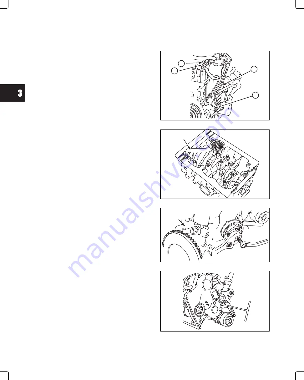
1. Remove the following parts, Fig. 1.

a. Glow plug wiring.
b. Glow plugs.
c. Injector pump bracket.
d. Remove fuel delivery lines.

Fig. 1 – Remove Fuel Delivery Lines

B

A

C

D

2. Remove the following parts, Fig. 2.

a. Remove oil pan and discard gasket.
b. Remove oil pick-up tube and strainer. Discard

gasket.

Fig. 2 – Removing Oil Pan

OIL PICK-UP

TUBE

3. Remove bell housing adapter screw if equipped.

and install flywheel holder, Tool #19418.

4. LEAVE TOOL INSTALLED.

a. Remove crankshaft pulley using Tool 

# 19420, Fig. 3.

Fig. 3 – Removing Crankshaft Pulley

FLYWHEEL

HOLDER

5. Remove timing gear cover, Fig. 4.

a. Discard timing gear cover gasket.

Fig. 4 – Removing Timing Gear Cover

Содержание MS-1055

Страница 1: ...FORM MS 1055 5 02 2002 BRIGGS STRATTON DAIHATSU LLC PRINTED IN U S A REPAIR MANUAL For 3 Cylinder Liquid Cooled Diesel Engines...

Страница 2: ...ENGINE SPECIFICATIONS AND DATA 4 FASTENER SPECIFICATIONS 9 BRIGGS STRATTON NUMERICAL NUMBER SYSTEM 10 MAINTENANCE SCHEDULE 11 ENGINE IDENTIFICATION NUMBERS The engine model and type number are located...

Страница 3: ...talled on the muffler The arrester must be maintained in effective working order by the operator In the State of California the above is required by law Section 4442 of the California Public Resources...

Страница 4: ...11 Injector pump 12 Engine Date code xxxxxxxx 13 Engine Model Type number xxxxxx xxxx xx 7 10 13 9 6 8 12 1 Thermostat 2 Oil filler cap 3 Turbocharger 4 Electric starter 5 Alternator 6 Oil pan Turbo c...

Страница 5: ...0 1 24 8 1 Compression pressure normal 300 RPM Bar Engine at operating temperature psi glow plugs removed 33 0 469 32 0 455 34 0 498 37 526 Compression pressure minimum 300 RPM Bar Engine at operating...

Страница 6: ...alve clearance cold Exhaust mm in 0 20 008 in Cylinder Block Cylinder block Mono block three cylinder cast iron Block Camshaft Camshaft Carbon steel Connecting rod Carbon steel Piston Pin Bearing Mach...

Страница 7: ...pecification 82 C 180 F Cooling Fan Drive V belt Cooling Fan Drive V belt FUEL SYSTEM Fuel Requirements Diesel fuel Cetane number 40 or higher Type Bosch VE distributor type Injector Pump Injector Tim...

Страница 8: ...mm 032 001 432447 0150 E2 522447 0105 E2 522447 0106 E2 522447 0107 E2 522447 0108 E2 522447 0109 E2 582447 0105 E2 582447 0125 E2 582447 0130 E2 582447 0131 E2 TABLE 1 Injection Pump Timing Engine Da...

Страница 9: ...47 0131 E2 582447 0231 E2 1700 50 3600 50 22100 87807 8U1 522447 0105 E2 1200 50 3850 50 22100 87807 8U1 522447 0108 E2 1600 50 3350 50 22100 87809 8U2 522447 0106 E2 1850 50 3420 50 22100 87809 8U2 5...

Страница 10: ...r 12 mm 25 0 Nm 220 in lbs Injector Pump mounting 12 mm 19 0 Nm 170 in lbs Injector Pump Drive Gear 19 mm 61 0 Nm 45 ft lbs Injector Pump Bracket 12 mm 19 0 Nm 170 in lbs Injector Nozzle 21 mm Deep 61...

Страница 11: ...t Carburetor Pneumatic or Mechanical Governor 8 Vertical Shaft Flo Jet Carburetor Mechanical Governor 9 Vertical Shaft Pulsa Jet Carburetor Pneumatic or Mechanical Governor 0 Plain Bearing DU Non Flan...

Страница 12: ...Change coolant D system Check fan belt D Service air cleaner D1 D2 4 D3 4 Engine Check cylinder head bolt torque D Check valve clearance D Electrical system Check battery electrolyte D Fuel system Cha...

Страница 13: ...linder Head 5 Valve Guides 6 Valves 7 DISASSEMBLE ROCKER ARM SHAFT 8 ASSEMBLE ROCKER ARM SHAFT 9 ASSEMBLE CYLINDER HEAD 10 INSTALL CYLINDER HEAD 11 ADJUST VALVES 14 BRIGGS STRATTON DAIHATSU 3 CYLINDER...

Страница 14: ...ing bracket screw b V belt c Fan if equipped Fig 1 Remove V belt And Fan C B A Fig 2 d Water pump e Exhaust manifold NOTE Remove exhaust system before removing exhaust manifold Fig 2 Remove Water Pump...

Страница 15: ...one complete revolution Valves will then have clearance Fig 6 Set Cylinder No 1 At TDC REFERENCE POINT TIMING MARK 3 Remove rocker arm assembly and push rods Fig 7 a Remove valve stem caps NOTE Mark...

Страница 16: ...alve Spring Seat 9 Valve Stem Seal 10 Valve Guide 11 Combustion Chamber 3 4 5 6 7 1 2 8 9 10 11 Remove valves Fig 10 1 Use valve spring compressor Tool 19417 to compress valve springs Remove the follo...

Страница 17: ...he same manner Use same specifications as cylinder head Fig 13 Check Cylinder Head For Distortion CHECK COMBUSTION CHAMBER Engine Model 522000 combustion chambers are not replaceable Engine Models 432...

Страница 18: ...Fig 17 Remove if damaged or if reject gauge enters valve guide Fig 17 Check Valve Guide Bushing REJECT GAGE 2 Remove valve guide bushing if required Fig 18 a Use bushing driver Tool 19367 and press o...

Страница 19: ...valve guide bushings first If valve guides are worn they must be replaced before refacing valve seats If valve seat is wider than dimension shown in Fig 21 a narrowing cutter should be used to ensure...

Страница 20: ...than 1 0 mm 040 in Replace if free length is less than 30 7 mm 1 209 in Fig 24 Check Valve Springs DISASSEMBLE ROCKER ARM SHAFT 1 Remove snap rings from ends of rocker arm shaft Remove set screw from...

Страница 21: ...Fig 26 Checking Rocker Arm And Shaft ASSEMBLE ROCKER ARM SHAFT 1 Oil all components before assembling Small grooves in rocker shaft next to oil holes must face down Assemble rocker arm components noti...

Страница 22: ...alve 8 Valve Spring Seat 9 Valve Stem Seal 10 Valve Guide 11 Push Rod 12 Rocker Arm Assembly 13 Rocker Arm Stud 3 4 5 6 7 1 2 8 10 9 NOTE When replacing rocker arm studs torque to 20 0 Nm 180 in lbs 1...

Страница 23: ...ad gasket over alignment dowels on cylinder block Fig 32 NOTE Make sure coolant oil passages and head bolt holes are aligned Fig 32 Install Cylinder Head Gasket ALIGNMENT DOWEL LOCATIONS 2 Install cyl...

Страница 24: ...ure rocker adjustment studs are seated in recessed end of push rods Fig 35 Install Rocker Arm Assembly 5 Install intake manifold with new gasket Fig 36 a Torque screws to 8 0 Nm 70 in lbs Fig 36 Insta...

Страница 25: ...m 170 in lbs Fig 39 Install Water Pump 2 Install water pump pulley Fig 40 3 Install fan if equipped a Torque screws to 7 0 Nm 60 in lbs Fig 40 Install Water Pump Pulley And Fan 4 Install V belt Fig 41...

Страница 26: ...earances With No 1 piston at TDC of compression stroke check and adjust valve clearances for cylinders shown in chart at right Rotate crankshaft one complete turn 360 clockwise to check and adjust rem...

Страница 27: ...ID COOLED DIESEL ENGINE REPAIR MANUAL MS 1055 Section 3 Timing Gears and Gear Case Section Contents Page REMOVE TIMING GEAR COVER AND GEARS 2 CHECKING GEARS 3 REMOVE GEAR CASE 4 REPLACE TIMING GEAR CO...

Страница 28: ...bracket d Remove fuel delivery lines Fig 1 Remove Fuel Delivery Lines B A C D 2 Remove the following parts Fig 2 a Remove oil pan and discard gasket b Remove oil pick up tube and strainer Discard gas...

Страница 29: ...exceeds 0 2 mm 008 check idler gear bearing and shaft for wear Fig 7 Reject Dimension Idler Gear ID 34 17 mm 1 345 Idler Gear Shaft OD 33 91 mm 1 335 a If idler gear bearing and shaft are within spec...

Страница 30: ...eplaced as a set Fig 9 Checking Injector Pump Timing Gear Backlash REMOVE GEAR CASE 1 Remove injector pump timing gear with a three jaw puller Fig 10 a Remove 2 nuts and injector pump Discard O ring F...

Страница 31: ...NOTE It may be necessary to rotate oil pump drive to engage oil pump rotors NOTE Position camshaft retainer so that center hole does not interfere with camshaft Note position length and number of scre...

Страница 32: ...mark 22 BB is aligned with timing mark 2 B on camshaft gear and timing mark 33 CC is aligned with timing mark 3 C on injector pump gear as shown in Fig 18 a Install oil pump gear Fig 18 Aligning Timi...

Страница 33: ...pick up tube and strainer with new gasket Torque to 8 0 Nm 70 in lbs a Apply a small bead of Permatex No 2 or similar sealant to crankcase areas shown Fig 22 b Install oil pan with new gasket c Torqu...

Страница 34: ...RETAINER AND FLYWHEEL 2 INSTALL OIL PAN 3 REMOVING PAN AND FLYWHEEL Drain oil from engine 1 Remove oil pan screws and nuts Remove oil pan and discard gasket Fig 1 Fig 1 Removing Oil Pan 2 Install flyw...

Страница 35: ...SEAL 1 Remove oil seal Fig 4 Fig 4 Removing Oil Seal 2 Lubricate outside diameter of oil seal a Using seal driver Tool 19424 install new oil seal Fig 5 Fig 5 Installing Oil Seal INSTALLING REAR SEAL...

Страница 36: ...screws a Torque flywheel screws to 47 0 Nm 35 ft lbs Remove flywheel holder Fig 7 Installing Flywheel INSTALL OIL PAN 1 Install oil pan with new gasket Fig 8 a Apply a small bead of Permatex No 2 or s...

Страница 37: ...AY 2002 BRIGGS STRATTON DAIHATSU 3 CYLINDER LIQUID COOLED DIESEL ENGINE REPAIR MANUAL MS 1055 Section 5 Cylinder Block Disassembly Section Contents Page ENGINE STAND FIXTURE 2 CYLINDER BLOCK DISASSEMB...

Страница 38: ...s required See drawings below for dimensions to make an engine stand mounting fixture The engine stand shown below is manufactured by Snap On 65 mm 80 mm 45 mm 39 mm 60 mm 107 mm 57 mm 45 mm 50 mm 65...

Страница 39: ...or Fig 1 Fig 1 Removing Starter And Bracket STARTER MOTOR 5 Remove alternator bracket and alternator Fig 2 Fig 2 Removing Alternator ALTERNATOR BRACKET 6 Remove valve lifters Fig 3 a Number lifters so...

Страница 40: ...r c Reassemble connecting rod cap to connect ing rod to prevent interchanging components Fig 5 Removing Connecting Rod Assembly 9 Remove crankshaft main bearing caps keeping main bearings with their r...

Страница 41: ...spect cylinder block for damage cracks and stripped threads Inspect cylinder bores for damage or scores 1 Check cylinder block deck for distortion Fig 1 Distortion Limit 0 08 mm 003 Fig 1 Checking Cyl...

Страница 42: ...s and pistons will fit perfectly and proper clearances will be maintained Fig 3 Checking Cylinder Bore MEASURE CYLINDER BORE IN SIX POSITIONS SHOWN TO DETERMINE TAPER OUT OF ROUND AREA OF NORMAL WEAR...

Страница 43: ...g 8 a Use a wood dowel or brass rod to prevent damage to camshaft bearing Fig 8 Removing Camshaft Plug 2 Install new camshaft plug using camshaft bearing driver Tool 19422 a Install camshaft plug flus...

Страница 44: ...D REPAIR 2 Remove timing gear oil nozzle Fig 11 Fig 11 Removing Oil Nozzle OIL NOZZLE 3 When re installing oil nozzle oil hole must be positioned at 45 angle pointing towards idler gear Fig 12 Fig 12...

Страница 45: ...be re ground or replaced 1 Check the main bearing and crankpin journals for wear and taper Fig 1 Standard size Main 41 976 42 000 mm 1 6526 1 6535 Crankpin 36 976 37 000 mm 1 4557 1 4567 Maximum out o...

Страница 46: ...journals must be clean and free of oil 1 With upper main bearings installed install crank shaft a Lay a strip of plastigage lengthwise on journal Fig 4 Do not lay plastigage across oil hole in cranksh...

Страница 47: ...ue to 36 0 Nm 320 in lbs Fig 8 DO NOT ALLOW CRANKSHAFT TO ROTATE Fig 8 Torque Rod Cap 3 Remove the connecting rod cap Measure the plastigage at its widest point Fig 9 If the clearance is not within sp...

Страница 48: ...g Camshaft Lobes 2 Measure camshaft journals Fig 12 STD Front 35 959 35 975 mm 1 4157 1 4163 Reject 35 890 mm 1 413 STD Center 35 910 35 955 mm 1 4138 1 4155 Reject 35 84 mm 1 411 STD Rear 35 910 35 9...

Страница 49: ...D RINGS 2 CHECKING PISTON PIN AND CONNECTING ROD 2 ASSEMBLE PISTON AND CONNECTING ROD 3 ASSEMBLE PISTON RINGS TO PISTON 4 DISASSEMBLE PISTON AND CONNECTING ROD 1 Remove compression rings and oil ring...

Страница 50: ...of rings and using the piston insert approximately 100 mm 3 9 into cylinder below ring travel Ring End Gap Reject Size Compression Rings Oil Ring 0 70 mm 0 028 0 70 mm 0 028 Fig 4 Checking End Gap CHE...

Страница 51: ...ication shown the connecting rod must be replaced Fig 8 Checking Crankpin Bearing End 4 Check for bent or twisted connecting rod Fig 9 NOTE Thrust faces must be free of any burrs or nicks or connectin...

Страница 52: ...a Install oil ring coil expander making sure wire is inserted fully into coil b Install oil ring c Install center compression ring then top compression ring with ID marks up Fig 11 Installing Piston R...

Страница 53: ...CRANKSHAFT Install main bearings in cylinder block Fig 1 NOTE Upper bearing has an oil groove and oil holes 1 Install upper main bearings in their respective saddles a Be sure bearing is seated in sad...

Страница 54: ...torque bearing caps one at a time in sequence shown to 58 0 Nm 43 ft lbs c Recheck crankshaft end play Crankshaft End Play 0 025 0 24 mm 0 0008 0 0094 NOTE After torquing bearing cap make sure cranksh...

Страница 55: ...rotates freely before proceeding to next cylinder Fig 6 Installing Piston And Connecting Rod ID MARK FRONT GENERAL ASSEMBLY 1 Install gasket oil pick up tube and strainer Fig 7 a Torque screws to 8 0...

Страница 56: ...number of screws as shown Fig 11 a M6 x 28 mm M6 x 1 1 4 b M6 x 16 mm M6 x 6 1 Torque screws to 8 0 Nm 70 in lbs Fig 11 Installing Gear Case B A A 3 Lubricate then install camshaft in cylinder block F...

Страница 57: ...522000 are equipped with right angle helical timing gears Timing marks are identified by letters A AA B BB etc instead of numbers The timing procedure is the same 7 With crankshaft key at 12 o clock p...

Страница 58: ...ulley with timing mark at 12 o clock position 1 cylinder Fig 19 NOTE Be sure alignment pin in crankshaft gear is seated in hole in pulley a Torque screw to 88 0 Nm 65 ft lbs b Remove flywheel holder F...

Страница 59: ...vers fuel to the injectors at a constant volume regardless of pump RPM The feed pump also circulates fuel through the pump for lubrication purposes A single pump plunger meters and distributes fuel in...

Страница 60: ...10 2 FUEL SYSTEM COMPONENTS FUEL FILTER INJECTOR FUEL DELIVERY LINE FUEL RETURN LINE FUEL RETURN LINE FUEL TANK INJECTOR PUMP FUEL LINE FUEL INJECTION SYSTEM COMPONENTS...

Страница 61: ...032 001 432447 0150 E2 522447 0105 E2 522447 0106 E2 522447 0107 E2 522447 0108 E2 522447 0109 E2 582447 0105 E2 582447 0125 E2 582447 0130 E2 582447 0131 E2 TABLE 1 Injection Pump Timing Engine Date...

Страница 62: ...e No 1 piston is at TDC compression stroke c If intake and exhaust valves do not have clear ance turn crankshaft pulley one complete revolution Valves will then have clearance Fig 2 Align Timing Marks...

Страница 63: ...sher Fig 6 a Torque screw to 17 0 Nm 150 in lbs 8 Install fuel delivery lines a Torque to 25 0 Nm 220 in lbs Fig 6 Install Distributor Screw DISTRIBUTOR SCREW Adjusting Injector Pump Timing Refer to t...

Страница 64: ...igns with reference point on gear case cover TDC Indicator should be within specification Fig 10 5 Torque injector pump mounting nuts and pump support bracket screw to 19 0 Nm 170 in lbs Fig 10 Verify...

Страница 65: ...ions listed are provided as an aid to the fuel injection specialist when testing injector nozzles 1 With injector installed on a nozzle tester operate the handle rapidly several times to clean off any...

Страница 66: ...king Spray Pattern Install Injectors Install injectors and fuel return line with new gaskets Fig 18 Install fuel delivery lines a Torque injectors to 61 0 Nm 45 ft lbs b Torque fuel return line to 27...

Страница 67: ...end of travel Fig 20 a Meter should make a continuous tone 3 Now lower float a Meter should display OL Replace drain plug and float sensor if not to specification Fig 20 Checking Sensor FLOAT FUEL SHU...

Страница 68: ...447 0131 E2 582447 0231 E2 1700 50 3600 50 22100 87807 8U1 522447 0105 E2 1200 50 3850 50 22100 87807 8U1 522447 0108 E2 1600 50 3350 50 22100 87809 8U2 522447 0106 E2 1850 50 3420 50 22100 87809 8U2...

Страница 69: ...be at operating temperature before adjusting idle speed Temporarily disconnect speed control wire at control bracket on pump 1 Remove and discard top no load wire and seal 2 Loosen top no load speed...

Страница 70: ...G SYSTEM 7 Test Equipment 7 Testing Alternator AC Output 8 Testing Regulator rectifier DC Output 8 Charging Indicator Circuit 9 Testing Charging Indicator Bulb And Wiring 9 40 AMP CHARGING SYSTEM 10 T...

Страница 71: ...OID Test Equipment 19 Testing Solenoid 19 Remove Solenoid 20 Remove Pinion And Clutch Assembly 20 Check Pinion And Clutch Assembly 21 Assemble Pinion And Clutch Assembly 21 Install Solenoid 22 Install...

Страница 72: ...LOW LIGHT PREHEATING TIMER GLOW RELAY FUEL FILTER WATER INDICATOR LIGHT CHARGE INDICATOR LIGHT B TERMINAL IG TERMINAL 3 4 5 6 7 1 2 8 IG TERMINAL L TERMINAL B TERMINAL L TERMINAL GLOW PLUGS KEYSWITCH...

Страница 73: ...H COIL BRAKE COIL Remove Glow Plug Disconnect glow plug wiring from connector 1 Remove glow plug connector nuts and connector 2 Remove glow plugs Fig 3 Handle glow plugs with care Do not drop Do not s...

Страница 74: ...ion 1 Insert BLACK meter test lead probe into terminal 4 2 Insert RED meter test lead probe into terminal 3 3 Turn keyswitch to On position a Glow light should light Meter should display 1 5 volts max...

Страница 75: ...29 The manual preheat keyswitch Part No 825129 is equipped with four positions and six terminals Fig 9 The G1 terminal provides current to the glow plugs only when the switch is in the Heat position W...

Страница 76: ...ator rectifier is equipped with a charging indicator light circuit NOTE The regulator rectifier requires a mini mum battery voltage of 6 volts to function There will be no charging output if battery v...

Страница 77: ...be installed on the negative terminal of the battery Fig 15 All connections must be clean and tight for correct amperage readings Attach meter test leads BEFORE starting engine The regulator rectifie...

Страница 78: ...ity complete circuit No tone indicates no continuity incomplete circuit An incomplete circuit will be displayed as OL Fig 17 Meter Setting Keyswitch must be in OFF position 1 Disconnect output harness...

Страница 79: ...Note The digital multimeter will withstand DC input of 10 20 amps for up to 30 seconds To avoid blowing fuse in meter the DC shunt is required Replacement fuse is available from your Briggs Stratton s...

Страница 80: ...Pulley 2 Remove nut and insulator at B terminal 3 Remove three screws and brush cover Fig 23 Fig 23 Remove Rear Cover B TERMINAL 4 Remove two screws then brush retainer assembly Fig 24 Important Leng...

Страница 81: ...10 Remove rotor from drive end housing Fig 28 Note Stator is NOT removable Fig 28 Remove Rotor ROTOR CHECKING BEARINGS Ball bearings must rotate freely If any rough spots are felt the ball bearing mus...

Страница 82: ...or continuity between slip rings as shown Fig 31 a Meter should make continuous tone continuity b If meter displays OL no continuity replace rotor 2 Check for continuity between slip ring and rotor sh...

Страница 83: ...Meter should beep once b If meter displays OL or makes a continuous tone diode is defective Replace rectifier 3 Repeat test at 2 3 and 4 terminals a Results must be the same Fig 35 Check Rectifier 4...

Страница 84: ...in lbs Fig 38 Assemble Housings 5 Align stator wires with holes in rectifier and assemble rectifier to brush end housing Fig 39 6 Carefully form a U bend in stator wires a Install screws and tighten...

Страница 85: ...m 10 Install rear cover and three screws Fig 43 a Torque screws to 3 0 Nm 25 in lbs 11 Install insulator and nut a Torque nut to 4 0 Nm 35 in lbs Fig 43 Install Cover Torque drive pulley using the fol...

Страница 86: ...cur they will be shown STARTER CURRENT DRAW TEST ALL Starter Installed Important When making the starter current draw test make sure that all parasitic load is removed from the engine and that engine...

Страница 87: ...lamp starter mounting bracket in a vise DO NOT clamp starter housing in a vise or field windings or magnets may be damaged Testing Starter No Load The No Load starter current draw test will be per for...

Страница 88: ...cable to a good ground such as drive housing Fig 51 2 Attach jumper wire to tab terminal on solenoid 3 Activate solenoid by contacting positive battery terminal with other end of jumper wire a Pinion...

Страница 89: ...r Motor 3 Remove two drive end cap screws Hold starter in vertical position with drive housing down and separate solenoid housing from drive housing Fig 54 Note position of solenoid return spring and...

Страница 90: ...pe starter a Clutch gear b Bearing retainer and roller bearings c Drive gear d Pinion shaft bearings e Return spring ball f Return spring Fig 57 Assembling Pinion And Clutch E F D A B C D 1 KW 1 2 KW...

Страница 91: ...drive housing Fig 61 a Torque screws to 9 0 Nm 80 in lbs 4 Install field coil wire a Torque nut to 8 Nm 70 in lbs Fig 61 Installing Starter Motor Replace Solenoid Plunger And Contacts Place starter i...

Страница 92: ...I 6 J 7 H 7 I 8 H 7 Install components in sequence shown Fig 65 Field Wire Terminal Side 1 A 2 B 3 C 4 D 5 E 6 F 7 G Battery Wire Terminal Side Before 99010100 1 0 KW After 98123100 1 0 KW Before 9808...

Страница 93: ...re damaged or worn replace armature Fig 67 Disassemble Starter Motor Inspect Armature Commutator The armature commutator may be cleaned with fine sandpaper DO NOT use emery cloth Commutator may be mac...

Страница 94: ...h retainer Fig 71 4 Contact first one negative brush then opposite brush with other test lead as shown a Meter should make continuous tone continuity b If meter does not make a tone no continuity repl...

Страница 95: ...ke sure brush wires are not grounding on brush retainer Fig 75 Assembling Motor Housing And Brushes 3 Align notch in end cap with rubber seal and install end cap Fig 76 a Make sure brush wires are not...

Страница 96: ...INDICATOR LIGHT RED GREEN YELLOW SOLENOID FUEL FILTER WATER INDICATOR LIGHT INJECTION PUMP GLOW PLUGS GLOW LIGHT PREHEATING TIMER GLOW RELAY KEYSWITCH LIGHT BLUE GREEN YELLOW BLACK RED LIGHT BLUE Reg...

Страница 97: ...CHARGE INDICATOR LIGHT B TERMINAL IG TERMINAL Wiring Diagram 40 Amp Alternator Typical 493625 Keyswitch With Fixed Preheat Timer and Glow Relay 3 4 5 6 7 1 2 8 IG TERMINAL L TERMINAL B TERMINAL L TER...

Страница 98: ...N YELLOW SOLENOID FUEL FILTER WATER INDICATOR LIGHT INJECTION PUMP GLOW PLUGS GLOW LIGHT Wiring Diagram 14 Amp Alternator Typical 825129 Keyswitch Manual Preheat LIGHT BLUE GREEN YELLOW BLACK RED LIGH...

Страница 99: ...ERY STARTER MOTOR SOLENOID INJECTION PUMP GLOW LIGHT FUEL FILTER WATER INDICATOR LIGHT CHARGE INDICATOR LIGHT B TERMINAL IG TERMINAL IG TERMINAL L TERMINAL B TERMINAL L TERMINAL GLOW PLUGS B S G1 G2 M...

Страница 100: ...p 4 ASSEMBLE GEAR CASE Install Oil Pump 7 Section Contents Recommended SAE Viscosity Grades C 34 STARTING TEMPERATURE RANGE ANTICIPATED BEFORE NEXT OIL CHANGE F 30 10 10 50 70 90 110 23 12 0 10 21 32...

Страница 101: ...every 200 hours of operation Change oil and filter more often if engine is operated in dusty or dirty conditions or if engine is operated under heavy loads or high ambient air temperatures Remove oil...

Страница 102: ...re gauge 4 Start the engine and allow it to reach normal operating temperature 5 Check oil pressure at 3000 RPM Oil Pressure 2 0 5 0 Bar 28 70 psi See charts below for troubleshooting guide Low Oil Pr...

Страница 103: ...ession stroke See Section 2 Remove V belt and fan if equipped Drain oil from engine NOTE Clean areas around fuel lines and injec tors to prevent dirt entry 1 Remove the following parts Fig 6 a Glow pl...

Страница 104: ...ter screw if equipped and install flywheel holder Tool 19418 LEAVE TOOL INSTALLED a Remove crankshaft pulley using Tool 19420 Fig 8 Fig 8 Removing Crankshaft Pulley FLYWHEEL HOLDER 4 Remove timing gea...

Страница 105: ...s c Remove timing gear case and discard gasket Fig 12 Removing Timing Gear Case A B B 8 Inspect rotors for wear or damage Fig 13 NOTE If pump rotors are worn or damaged replace the gear case Fig 13 In...

Страница 106: ...r case with new O ring and install nuts and support bracket screw finger tight Fig 17 NOTE Pump must be able to rotate a Align timing mark on injector pump with timing mark on gear case NOTE See Secti...

Страница 107: ...nd nuts to 8 0 Nm 70 in lbs Fig 20 Installing Timing Gear Cover B C A A B D C D C C 9 Install crankshaft pulley with timing mark at 12 o clock position 1 cylinder Fig 21 NOTE Be sure alignment pin in...

Страница 108: ...ivery lines to 25 0 Nm 220 in lbs Fig 23 Fig 23 Installing Fuel Delivery Lines 12 Install V belt Fig 24 13 Install alternator bolts A and B Belt deflection limit is 10 12 mm 10 kg 3 8 1 2 in 22 lbs a...

Страница 109: ...su gasoline and diesel engines use a pressurized forced circulation cooling system The water pump circulates coolant through the cylinder block cylinder head and radiator The thermostat maintains opti...

Страница 110: ...eze plugs cylinder block and cylinder head If system does not maintain pressure and no leaks are evident externally check for an internal leak such as a blown head gasket warped cylinder head or cylin...

Страница 111: ...make sure thermostat valve is fully closed 2 Immerse thermostat in water and heat water gradually Fig 4 3 Note temperature when thermostat starts to open a 81 84 C 178 183 F 4 Note temperature when th...

Страница 112: ...pump shows evidence of leaking or bearings are rough replace the water pump NOTE Most water pump and cooling system failures result from using straight water as a coolant Without water pump lubricant...

Страница 113: ...all thermostat and coolant outlet with new gasket Fig 11 a Torque screws to 8 0 Nm 70 in lbs 4 Install temperature gauge wire if equipped 5 Install radiator hoses Fig 11 Installing Coolant Inlet And O...

Страница 114: ...RMATION 2 Turbocharger Lubrication System 2 Turbocharger Cooling System 3 Turbocharger Waste Gate 4 Turbocharger Pressure Control System 4 Crankcase Blow by Recirculating System 5 CHECKING WASTE GATE...

Страница 115: ...ort diameter of the oil inlet line The oil inlet line is installed with union screws at the cylinder head and the turbocharger Oil returns to the cylinder block via the oil outlet line Fig 1 Lubricati...

Страница 116: ...r is supplied from the rear right of cylinder block and returns to the water pump inlet Fig 3 Cooling System of Turbocharger 1 COOLANT INLET LINE COOLANT OUTLET LINE Fig 4 Cooling System of Turbocharg...

Страница 117: ...LVE Turbocharger Pressure Control System As pressure in the turbocharger rises the actuator for the waste gate valve opens allowing some of the exhaust gases to bypass the turbocharger Fig 6 Turbochar...

Страница 118: ...Disconnect the waste gate actuator hose at the actuator 2 Connect pressure vacuum pump Tool 19493 3 Apply pressure of 14 2 psi 0 9 bar and ensure that the rod and link operate 4 When pressure is relea...

Страница 119: ...s raised rapidly it may cause damage to the turbocharger bearing e Check oil and coolant lines for leaks f Special heat treated mounting fasteners are used on the turbocharger Do not substitute Fig 9...

Страница 120: ...move Clamp TIE STRAP TAB 3 Disconnect the air intake tube at the turbocharger 4 Disconnect the air intake tube from the air intake pipe AIR INTAKE TUBE Fig 14 Disconnecting Air Intake Tube 5 Remove th...

Страница 121: ...TLET HOSE 8 Remove coolant inlet line bracket screw Fig 18 Remove Clamp BRACKET 9 Remove two nuts then remove coolant line assembly from turbocharger Fig 19 Removing Coolant Line 10 Remove oil inlet l...

Страница 122: ...e bracket screw at the exhaust manifold Fig 22 Removing Bracket Bolt 13 Remove two screws from turbocharger and pull out the oil outlet tube from the cylinder block Discard O ring and gasket Fig 23 Re...

Страница 123: ...GER 1 Check blades of turbine and compressor for damage 2 Rotate the blades by hand and ensure that they turn freely without contacting the housing 3 Check that oil is not leaking at the turbine side...

Страница 124: ...s until the flange surfaces of the turbocharger exhaust manifold and turbocharger stay in contact each other b First torque nuts to 34 0 Nm 25 0 ft lb c Then torque screws to 29 0 Nm 20 0 ft lb Fig 30...

Страница 125: ...e union screws and bracket screw Union screws Cylinder head side Turbocharger side 44 0 Nm 18 0 Nm 170 in lb 32 0 ft lb Bracket screw 19 0 Nm 170 in lb Fig 32 Installing Oil Inlet Line Fig 33 Installi...

Страница 126: ...all clamps with tabs as shown Fig 37 Install Coolant Inlet Hose A YELLOW MARK B 9 Install air intake pipe a Torque nuts to 13 0 Nm 115 in lbs Fig 38 Installing Air Intake Pipe AIR INTAKE PIPE 10 Align...

Страница 127: ...g Clamp PIPE BREATHER TUBE INSTALLATION OF COOLANT INLET TUBE 1 Apply sealer to the portion of tube that is to be installed in cylinder block 2 Align the center of tube with the center of M10 thread a...

Страница 128: ...FORM MS 1055 5 02 2002 BRIGGS STRATTON DAIHATSU LLC PRINTED IN U S A REPAIR MANUAL For 3 Cylinder Liquid Cooled Diesel Engines...

Отзывы: