background image

9 / 16

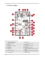
19 Humidity indoors

20 Room climate Indicator

21 Sensor signal status

22 Sensor symbol

23 Wind/storm classification

24 Wind direction

25 Index (heat/dew point/UV/Beaufort)

26 Index value

27 Weather trend

28 AM/PM information in 12-hour time mode

7 Before starting operation

NOTICE

Avoid connectivity disruptions!

To avoid connectivity disruptions between the devices, consider the following points before starting
operation.

1. Place base station (receiver) and remote sensor (sender) together as close as possible.

2. Set up power supply for the base station and wait until the indoor temperature is displayed.

3. Set up power supply for the remote sensor.

4. Position the base station and the remote sensor within the effective transmission range.

5. Ensure that the base station and remote sensor are assigned to the same channel.

When changing batteries always change batteries in the main unit as well as all remote units and re-
place them in the correct order, so the remote connection can be re-established. If either of the
devices is mains-powered, the power supply must be disconnected for a short moment also for this
device when exchanging the batteries. If batteries are exchanged in only one of the devices (i.e. the
remote sensor) the signal can’t be received or can’t be received correctly.

Note, that the effective range is vastly affected by building materials and position of the main and re-
mote units. Due to external influences (various RC devices and other sources of interference), the
maximum distance can be greatly reduced. In such cases we suggest to position the main unit and the
remote sensor at other places. Sometimes all it takes is a relocation of one of these components of a
few inches! Though the remote unit is weather proof, it should be placed away from direct sunlight,
rain or snow.

8 Setting up power supply

Base unit

1. Remove the battery compartment cover.

2. Insert the batteries into the battery compartment. Ensure that the battery polarity (+/-) is correct.

3. Replace the battery compartment cover.

Remote sensor

4. Loosen the screw at the battery compartment cover with a small Philips screwdriver and remove

the cover.

5. Insert the batteries into the battery compartment. Ensure that the battery polarity (+/-) is correct.

6. Replace the cover and retighten it with the screw.

Содержание 7002570

Страница 1: ...Weather Station PC Weather Station with multifunction sensor EN Instruction manual...

Страница 2: ......

Страница 3: ...display 8 7 Before starting operation 9 8 Setting up power supply 9 9 Attaching rubber pads 10 10 Assembling and installing the multifunctional remote sensor 11 11 Signal transmission 12 12 Time synch...

Страница 4: ...nufacturer The terms and brand names of the respective companies used in this document are protected by brand patent or product law in Germany the European Union and or other countries 2 Validity info...

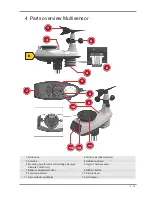
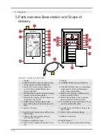
Страница 5: ...nd vane 2 Wind cups Anemometer 3 Antenna 4 Radiation shield 5 Mounting hole for vertical mounting pole pipe diameter 35 40 mm 6 Hygro Thermal sensor 7 Battery compartment door 8 RESET button 9 Functio...

Страница 6: ...urrent value display 8 BARO button display of different atmo spheric pressure values 9 WIND button display change between av erage and current gust 10 RAIN button display change between daily weekly a...

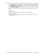
Страница 7: ...B A plug PC Weather data transmission requires a PC with Windows 7 or higher and installed WEATHER TOOL software Scope of delivery Base station A outdoor sensor multifunctional remote sensor B USB cab...

Страница 8: ...2 Alarm enabled 3 Sync icon time 4 Date day month or reverse 5 Weekday 6 Moon phase 7 Bar chart for value display 8 Air pressure alarm enabled 9 Air pressure 10 Sunrise time 11 Sunset time 12 Wind spe...

Страница 9: ...ered the power supply must be disconnected for a short moment also for this device when exchanging the batteries If batteries are exchanged in only one of the devices i e the remote sensor the signal...

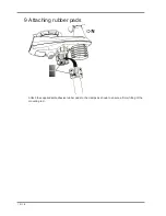
Страница 10: ...10 16 9 Attaching rubber pads Attach the supplied self adhesive rubber pads to the clamps as shown to ensure a firmer fitting of the mounting rod...

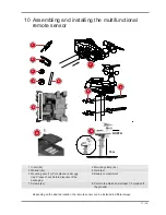
Страница 11: ...2 Mounting clamp 4x 3 Washer 4x 4 Nuts 4x 5 Mounting pole 1x Pole placed under egg tray Please check before disposal of the packaging 6 Battery compartment 7 Screws 4x 8 Point to the North and at leas...

Страница 12: ...the supplied USB cable Proceed as follows 1 Put the microUSB plug of the USB cable into the USB slot of the device 2 Put the USB A plug of the cable into a free USB port of the computer 3 Turn on the...

Страница 13: ...uipment type with item number 7002570 is in compli ance with Directive 2014 30 EU The full text of the EU declaration of conformity is available at the following internet address www bresser de downlo...

Страница 14: ...14 16 You can consult the full guarantee terms as well as information on extending the guarantee period and details of our services at www bresser de warranty_terms...

Страница 15: ......
Страница 16: ...e mail e mail sav bresser fr T l phone 33 494 592 599 BRESSER France SARL P le d Activit s de Nicopolis 260 rue des Romarins 83170 Brignoles France Prix d un appel local depuis la France ou Belgique S...

Отзывы: