


- 6 -
General Information
About this Instruction Manual
Please read the safety instructions in this manual carefully. Use this product only
as described in the manual to avoid damage to the device or injury. Keep the
operating instructions in a safe place so that you can always keep up to date on
all the operating functions.
DANGER!
You will find this symbol before every section of text that
deals with the risk of minor to severe injuries resulting from
improper use.
ATTENTION!
You will find this symbol in front of every section of text which
deals with the risk of damage to property or the environment.
Designated use
This device is for personal use only.
It was developed for a magnified representation of observations of nature.
General warnings
RISK OF BLINDNESS!
Never look directly at, or near to the sun with this device. There is a RISK
OF BLINDNESS!
DANGER OF SUFFOCATION!
• Children must only use the device under adult supervision. Keep
packaging materials (plastic bags, rubber bands, etc.) away from child-
ren! There is a DANGER OF CHOKING!
FIRE HAZARD!
Do not expose this device - especially the lenses - to direct sunlight!
Focusing of sunlight could cause fires.
ATTENTION!
Do not disassemble the device! In the event of a defect, please contact
your dealer. They will contact the Service Center and can arrange the
return of this device for repair if necessary.
Do not expose the device to high temperatures.
Protect privacy!
The binoculars are intended only for private use. Respect the priva-
cy of your fellow human beings - do not look into private flats with
this device, for example!
All parts (Fig 1-3)
b
Telescope tube
c
LED viewfinder
d
Adjustment screws
e
Tube opening
f
Objective
g
Eyepiece socket
h
Focus wheel (focus adjustment)
i
Tube clamp
j
Mounting
1)
Accessories tray
1!
Locking screws (tripod)
1@
Dust cap
1#
Tripod Leg
1$
Flexible shaft for declination adjustment
1%
Flexible shaft for rectascension adjustment
1^
Tripod spider
1&
Counter rod
1*
Eyepiece
1(
Upright Prism
2)
Barlow Lens
2!
T2-Adaptor M42 x 0,75mm*
2@
Smartphone Adaptor
*camera specific T2 ring additionally required, not included in the delivery
Parts (Fig15): Mounting
A
Tube clamp
B
Focusing on the focus wheel
C
Scale of the declination-axis
D
Declination axis fixing screw
E
Fine-adjustment of the declination-axis
F
Latitude setting scale
G
Fixing and adjusting screw of the latitude setting
H
Counterweight with locking screw
I
Fixing screw of the right ascension axis
J
Right ascension axis scale
K
Fine-adjustment of the rectascension-axis
L
Fixing screw for horizontal alignment
M
Bracket for optional tracking motor
N
Clutch for disengaging the engine
O
Transmission gear for tracking motor
TIP:
The right ascension axis (Fig 16 green line) is also called the
hour axis.
The declination axis (Fig 16 blue line) is also called the
elevation axis.
i
Part I - The Structure
1. General information about the structure and the choice of location
Before you begin the assembly, you must choose a suitable location for your
telescope. It helps, if you set up this instrument in a location, where a clear view
of the skies, a stable footing and sufficient space around you are given.
First, remove all the parts from the packaging. Using the diagram, check whether
all the parts are included.
ATTENTION!
Only tighten the screws with care "hand-tight" to avoid
"overtightening" the screws. This can cause damage to the
screws and threads
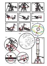
2. Set up tripod
The tripod legs are pre-assembled and already connected to the tripod head (Fig
5, X) and the tripod spider (Fig 1, 16).
Remove the tripod from its packaging and place it vertically with the tripod feet
facing down. Now take two of the tripod legs and carefully pull these tripod legs
apart to the fully open position. The entire weight of the tripod rests on one leg.
Then set up the tripod straight.
Now pull out each tripod leg individually to the desired length (Fig 4) and now
turn one each of the clamping screws (Fig 4, 11) 3 pieces hand-tight. Do not
overtighten the screws! The clamping screws are used to lock the inner tripod leg
segments at the desired height.
TIP:
A small spirit level on the accessory tray can help you set up your
tripod level.
i
3. Insert mount
Next, attach the mount (Fig 1, 9) to the tripod head (Fig 5, X). To do this, insert
the mount into the top of the tripod head and hand-tighten the thumbscrew
from below.
The mount (Fig 1, 9) is assembled by sliding the weight on to the weight rod (Fig
7, X) and screwing it firmly in to the thread of the mount from below.
The mount is completed by placing the tube clamp (Fig 1+3, 8) on the mount and
securing it with the screw (Fig 8, X).
Maksutov optics do not have a tube clamp. The rail is placed directly on to the mount.
4. Mount shelf
The accessory tray (10) is placed on the tripod spider with the flat side down and
locked by turning the tray approx. 60° clockwise (Fig 6). The three pegs of the
tray should be centred in the receptacles of the tripod struts and snap into place.
5. Mounting the tube
To mount the telescopic tube (Fig 1, 1), first loosen the screws of the tube clamps
(Fig 9, X) on the holder and open the clamps.
Содержание 0115660
Страница 1: ...Instruction manual First Light Refracting telescope Art No 0115660 ...
Страница 11: ... 11 Notes ...